
Owner's manual

Using Transfer Line Cycles
Chapter 31
31-43
Template 12: Back Boring Cycle
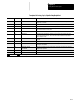
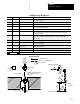
Letter Paramacro Label Description
G 500
G90/91 G-codes G90orG91 for absoluteorincrementalmodes. Atthis time onlyabsolute
mode,G90,is available.
X,Y 501, 502
HOLE POSITION X, Y The location to which the tool moves beforeitbeginsa boring operation.
X 503
DEPTH OF HOLE The location to which the toolboresintothe part.
R 504
CLEAR POSITION The location thatthe tool retractstoafteran operation.Itiscompletelyfree ofthe
part.Thisalso known astheR plane.
X,Y 505, 506
RETURN POSITION X,Y The location wherethe controlsstarts and stop s a cycle.
F 507
FEEDRATE The feedrate fordrilling/boringoperations, and allmovesrepresented by the solid
linesintheQuickViewscreens. This is also the maximumfeedrateforoperations
that use adaptive depth.
Q 508
SHIFT AMOUNT The amountof distancethat spindle shifts along the AMPed axis. The axis thatthe
spindleorientstoafterthecut issetinAMP. This cannotbeusediftheIand J
words are used.
X 511
TOOL CHANGEPOSITION The location the controlmoves to sothatatoolchangemaybe performed.
I 512
HARD STOP SENSE ZONE Once itreachesthislocation,thecontrolknowstoexpecta hard stop before
reaching the holebottom.
I 513
ADAPTIVE DEPTH
INCREMENT
The amountofdistance thatthecontrol willincrementthetoolinto the partduringan
adaptive depth operation.
M 514
M03/M04 The M--code usedtoturn the spindle clockwise orcounter-clockwise.
S 515
SPINDLE SPEED The speedofthespindle.Measuredin revolutions perminute.
Required entry Optional entry
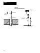
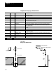
Figure 31.15
Back Boring Cycle
Spindle
orientatio
n
Spindle orientation
Spindle orientation forward
after returning to initial
point level
Spindle rotation forward
1
2
3
4
5
6
7
8
Cutting feedrate
Maximum cutting feedrate
Shift amount
Depth of Hole
Clear Position
Hole Position
Return
Position