
Owner's manual

Using Transfer Line Cycles
Chapter 31
31-32
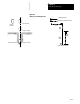
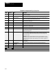
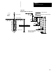
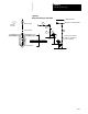
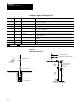
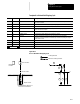
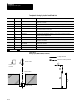
Template 4: Deep Hole Drill Cycle, Chip Break
Letter Paramacro Label Description
G 500
G90/91 G-codes G90or G91 for absoluteorincrementalmodes. Atthis time onlyabsolute
mode,G90,is available.
X,Y 501, 502
HOLE POSITION X, Y The location to whichthetoolmovesbefore itbeginsa drilling operation.
X 503
DEPTH OF HOLE T h e locationtowhich the tool drillsintothepart. Ifthe cycle uses adaptive depth,this
position needsto be beyond the adaptive depth increment.
R 504
CLEAR POSITION The locationthatthe toolretracts to afteranoperation.Itis completely freeofthepart.
Thisalso known astheR plane.
Q 505
INFEED AMOUNT Thisdefines the infeed amountforeachstepinto the hole
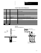
X,Y 506, 507
RETURN POSITION X,Y The location where the controls startsand stopsa cycle.
F 508
FEEDRATE Thefeedratefordrilling/boringoperations. This is alsothemaximumfeedrate for
operationsthatuseadaptive depth.
P 509
AMOUNT OF DWELL The amountoftime the axispausesbefore itretractsfromthehole;measured in
seconds.
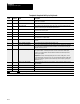
X 510
TOOL CHANGEPOSITION The location wherethe controls starts and stops acycle.
E 511
ADAPTIVE FEED MINIMUM Thisistheminimumfeedrateatwhichthecontrol performsan adaptivefeedoperation.
The controlwilltrytomaintain thisminimumfeedrate,evenifitmeans increasingthe
adaptive feed torquepercent.
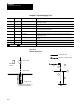
Q 512
ADAPTIVE FEED TORQUE % This is the amountof theselected servo’scontinuousrated torqueasentered inAMPby
yoursysteminstaller. Valid ranges are from1 to 150% oftheservo’srated torque.
Refertoyoursysteminstaller’s documentationfordetailson the rated torque ofthe
servos in your system.
Important:Thetorque amountapplied bytheservo isnotthecuttingforce. Itisthe
torque applied bytheservotothe axis. You mustcalculatetheequivalentcutting force
basedon yourmachine dynamics(motorrated torque,leadscrew pitch,gearing,tool
dimensions, etc...).
I 513
HARD STOP SENSE ZONE Once itreachesthislocation,thecontrolknows toexpecta hard stop beforereaching
the holebottom.
I 514
ADAPTIVE DEPTH INCREMENT T he amountofdistancebetween the surfaceofthepartandthedepthofhole.
M 515
M03/M04 The M--code usedtoturn the spindle clockwise orcounter-clockwise.
S 516
SPINDLE SPEED The speed ofthespindle.Measuredin revolutions perminute.
Required entry Optional entry
d-This value iswritten into the cycle. Itis .01inches (.254 mm).