
Owner's manual

Chapter 30
Using a 9/Series Dual--processing System
3
0
-
2
2
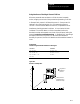
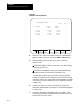
This is a representation of the basic format for modifying the tables.
G10 L{}P__ X___ Z___ I___ K___;
5
6
Where :
Is :
L(5-6)
The definition ofwhich area inthetableisbeing modified.
L5 - Modifies the Area1 values
L6 - Modifies the Area2 values
P
The boundary numberoftheinterference boundary thatishaving itsvalues changed is
specified following the Paddress.
X
The value to add to(inG91 mode) orreplace (inG90 mode)the positive Xaxisvalue. This
valueis alwaysa radius value.
Z
The value to add to(inG91 mode) orreplace (inG90 mode)the positive Z axis value.
I
Xaxisintegrand. The value to addto(inG91 mode)orreplace(inG90 mode)thenegative X
axisvalue. This value isalwaysa radius value. IistheintegrandwordoftheX axis.
K
Z axis integrand. The valuetoadd to (inG91 mode)orreplace (inG90 mode)the negative Z
axisvalue. K is the integrandwordoftheZ axis.
Programming this G10 code can change only the table values for the
process that has the G10 part program currently active. You must run
separate G10 programs in each process to set up each area.
Important: G10 blocks cannot be programmed when TTRC is active.