
Owner's manual


OffsetTables and Setup
Chapter 3
3-2
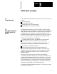
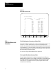
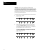
Figure 3.1
Offset Table Screen for Wear
SEARCH
NUMBER
REPLCE
VALUE
ADD TO
VALUE
ACTIVE
OFFSET
MORE
OFFSET
TOOL OFFSET NUMBER:
TOOL WEAR TABLE X PAGE 1 OF 4
NO. LENGTH (DIAMETER)
1 .5321 .0234 [INCH]
2 .4421 .0142 [INCH]
3 .0243 .0888 [INCH]
4 .0156 .0791 [INCH]
5 .0265 .0532 [INCH]
6 .081 .043 [ MM ]
7 .032 .022 [ MM ]
8 .0000 .0000 [INCH]
9 .0000 .0000 [INCH]
10 .0000 .0000 [INCH]
11 .0000 .0000 [INCH]
12 .0000 .0000 [INCH]
13 .0000 .0000 [INCH]
Tool Offset Numbers (Geometry and Wear Table)
Tool offset numbers are called out in a part program through use of D-- and
H--words. D-- and H--words specify a one, two, or three digit offset
number. The control then accesses the value assigned to that offset number
in the offset t able. The offset number is in t he far left column on the offset
screen. Offset number “00”is not a valid offset number to enter data under,
but can be used to cancel tool offsets.
For more on calling offset numbers refer to chapter 20.
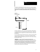
ToolLength Offset Data (Geometry Table)
The tool length offset function is used to compensate for the difference
between the tool position (or tool length) as mounted in the spindle and the
tool length assumed in writing a part program. By using the tool length
offset function, a programmer can write a part program without further
concern for tool mounting.
3.1.1
Tool Offset Dimensional
Parameters