
Owner's manual


Paramacros
Chapter 28
28-28
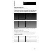
#5095 to 5096
Probe stylus Length and Radius
These parameters correspond to the values set in the probing cycle
parameter table discussed in chapter 27. When values are assigned to these
parameters, the current values in the probe table is replaced.
5095 Probe stylusLength
5096 Probestylus Radius
For details on probe radius and length parameters, see chapter 27 on tool gauging.
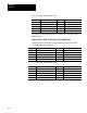
#5101 to 5112
Current Following Error
These parameters a re read-only. They correspond to the current following
error for an axis.
5101 Axis 1 following error 5107 Axis 7 following error
5102 Axis 2 following error 5108 Axis 8 following error
5103 Axis 3 following error 5109 Axis 9 following error
5104 Axis 4 following error 5110 Axis 10 following error
5105 Axis 5 following error 5111 Axis 11 following error
5106 Axis 6 following error 5112 Axis 12 following error
The system i nstaller determines in AMP the name (or word) that is used to
define the axis. The following error of a system constantly changes. You
can use this parameter to take a “snapshot”of the following error, but the
value that is read may not the current following error of the system.
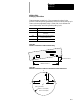
#5201 to 5212
External Offset Amount
These parameters are read or write. They correspond to the current value
set in t he work coordinate table for the external offset (see chapter 3). This
allows the reading of data from the tables and also the setting of data into
the table by assigning values to the parameters.
5201 Axis 1offsetamount 5207 Axis7 offsetamount
5202 Axis 2offsetamount 5208 Axis8 offsetamount
5203 Axis 3offsetamount 5209 Axis9 offsetamount
5204 Axis 4offsetamount 5210 Axis10offsetamount
5205 Axis 5offsetamount 5211 Axis 11 offsetamount
5206 Axis 6offsetamount 5212 Axis12offsetamount
The system i nstaller determines in AMP the name (or word) that is used to
define the axis. Changes made to the external offset using this paramacro
variable go into effect only after the axis has been re-homed, or power to
the control has been cycled.