
Owner's manual

Skip, Gauge, and Probing Cycles
Chapter 27
27-19
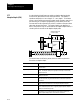
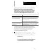
Format for an adaptive depth block is as follows:
G26
X__
Y__
Z__
I__
J__
K__
;
Where: Programs:
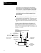
X,Y,or Z Adaptive Depth Axis word. Use the axiswordassociated withtheadaptive
depth(the systeminstallerselectsthisaxis asthe controllingaxis inAMP).
Programan axis destination thatissufficientlybeyondwhereyou expectthe
depth probetocontactthepartsurface. Thisposition shouldbe farenough
beyondtheprobecontactpointso asno deceleration occurs beforethe
probefires. This destination canbe programmed aseither an absolute or
incremental value(G90orG91 mode). Only oneaxiswordcan be
programmed ina G26block.
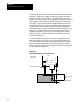
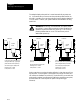
I, J, or K Axisintegrand. Use theaxisintegrand forthe adaptive depth axis. Program
an incrementaldistance equaltotheamountofdeflection youwantthe
adaptive depth probe to depress. Since this integrandvalueis unsigned,the
incremental deflection programmed here isin the same direction ofmotionas
whenthetrip occurs. T his should be the actualdepthofthe holebeyond the
partsurface. Thisaxisintegrand word isalwaysan incrementalvalue. T he
resolutiontowhichyou can programthisword isdependanton the adaptive
depth axiswordformat.. You may be abletoprogram thisdepthwith greater
accuracythantheaxis isnormally capable of. The system installeralso sets
the maximumallowable adaptive depth probe deflection inAMP. This value
isalso themaximum value fortheintegrand.
WARNING: The system installers maximum value for probe
deflection is relative to the probe zero point. It is not an
absolute value. Don’t allow a large amount of probe deflection
where you establish the zero point. The larger this deflection,
the greater chance that you will exceed the maximum deflection
your probe can withstand thus nullifying your machine tool
builders m aximum probe deflection.