
Owner's manual

Skip, Gauge, and Probing Cycles
Chapter 27
27-12
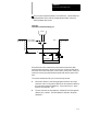
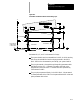
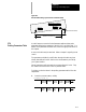
The purpose of this cycle is to provide a means to measure the amount that
a part is out of parallel (or rotated) with a selected axis through the use of a
touch probe. Note that the currently active plane (G17, G18, or G19) must
be the same plane in which probe motion is to occur in and must be active
before the probing cycle block is executed.
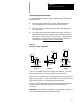
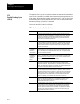
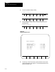
Format for the G38.1 code is as follows:
G38.1 X__ Y__ I__ J__ R__ D__ E__ F__;
Where : Is :
X
Anyvalidaxisnamefollowed bythecoordinate positionofthefirstmeasuring
pointonthataxis. May be an absolute orincremental,signedvalue. Being the
firstaxisword intheG38.1blockindicates thatthis axisistheone fromwhich
measurementsare to be taken. The G38.1 probing cycle will determine how
muchthe partis outofparallelwiththis axis
Y
The name ofanyaxisthatis perpendiculartothefirstaxisintheG38.1block.
Maybe an absolute orincremental,signedvalue. Parallelismwillbe measured
bymovingtheprobealong thisaxistotheedge ofthe part. The valueentered
with this parameterdefines the expected positionon this axis where the probe
willhitthe edgeofthepart.
I
(integrandof
first axis in
G38.1 block)
The incrementalsigned distancebetweenthefirstandsecond probe hits. This
incremental distanceis measuredalong the firstaxis programmedin the G38.1
block. Inthis manual Iisthe integrandwordforthe Xaxis. The integrandword
for anaxisis determined in AMP.
J
(integrandof
secondaxis
inG38.1
block)
The estimated amountthe partis outofparallel. J isan incremental,signed
distance. Jisadded to the coordinatevalueentered with the second axisin the
G38.1 blockforthe second probehitonly.
The net result istoshiftthe tolerance
band (programmed with the Dword)bythe amountJ.
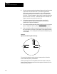
R
The incrementalunsigned approach distance. Thisparameterdetermines the
distance the second axisin theG38.1blocktravels atthe Efeedrate when
probing towardsthepart. Afterthisdistance isreachedtheprobeslowstotheF
feedrate.T his parameter is optional. Ifnotentered,the controlwilldefaulttothe
valueentered intheprobingtable discussed insection 27.5.
D
The tolerance band distance. The value entered forD definesa bandon both
sidesoftheexpected endpointenteredwith the Yparameter. Enteravalue for
this parameter defininga tolerancedistance oneither side ofthe expected probe
triggering point(Y above). Thisparameterisoptional,butmusthave apositive
valueifprogrammed. If notprogrammed,the controlwilldefaulttothevalue
entered in thep robing cyclepa rametertable discussed insection 27.5.
E
The approach feedrate. Entera value for thisparameterthatdefinesthe feedrate
usedtoreachtheapproachdistance (R). This parameter is optional. Ifnot
entered,the controlwill defaulttothe value enteredin the probing cycle
parametertable discussed in section 27.5.
F
The probe feedrate. Entera value for thisparameterthatdefinesthefeedrateat
whichtheprobeistomoveafterpassingthepointdefined bytheR parameter.
The probe continueson atthis feedrate untilcontacthasbeenmade withthe
edge of thepartorthe toleranceband isexceeded. This parameter is optional.
If notentered,thecontrol will defaultto the valueentered intheprobing cycle
parametertable discussed in section 27.5.
27.5
Parallel Probing Cycle
(G38.1)