
Owner's manual

Skip, Gauge, and Probing Cycles
Chapter 27
27-10
3. The axis continues towards the e stimated diameter (H) until the probe
signals that contact has been made. If the probe triggers before
reaching the negative t olerance band (D), or does not trigger after
passing through the positive tolerance band (D), a PROBE ERROR
will occur. This error appears on the screen as a warning but does not
place the control in E-STOP. Instead the G38 block is aborted, and
program execution proceeds to the next block.
4. If the probe triggers within the tolerance band, the position is
recorded, and the axis returns to the start-point of the probing
operation at the approach feedrate (E).
5. The control repeats the preceding steps on the first axis
in the c urrent
plane. If the plane is the XY plane, then this would be the X axis.
6. After successfully probing in the positive direction of the first axis in
the current plane, the control will then probe in the negative direction
of the first axis. In all, three points are measured for determining the
circle’sradius.
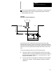
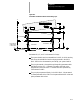
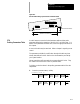
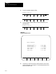
Figure 27.3
Typical Probe Path During G38 Hole Probing
+X
-- X
+Y
4
3
2
1
56
The control calculates t he actual radius and center position of the hole
from the three data points just measured.
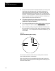
After the probing moves are completed and the hole center location has
been calculated, the axes are positioned at the approach feedrate (E) to the
exact hole center location.