
Owner's manual


Skip, Gauge, and Probing Cycles
Chapter 27
27-3
Format for a ny G31 external skip blocks is as follows:
G31 X__ Y__ Z__ F__;
Where : Is :
G31
AnyoftheG codes intheG31 seriesorG04. Usetheone thatisconfigured to
respond tothe currentexternalskip signal device thatisbeing used.
X, Y, Z
The endpointof themoveifno externalskipsignalisreceived. These also
determinethe directionthatthe toolwilltravel in.
F
The externalskipfunctionfeedrate. Ifnovalueis enteredhere,the externalskip
functionwillexecute ateitherthecurrentlyactive feedrate,orthefeedrate
defined for itin AMP(basedon whethertheAMP parameter Use AMPSkip
Feedrate is set to ”NO”or ”YES”). A value entered here replaces the currently
active feedrate andsupersedesthe AMP defined feedrate.
The G31 series of G codes always produce linear motion regardless of the
current mode active at their execution. After their completion the control
returns t o the operating mode active before the external skip block was
read (G00, G01, G02, G03).
Important: The move that immediately follows a G31 series external skip
block cannot be a c ircular move.
The coordinates of the axes when the external skip signal is received are
available as the paramacro system parameters #5061-#5066 (work
coordinate system) a nd #5071-#5076 (machine coordinate system). These
values will have been adjusted to compensate for the probe tip radius if a
radius compensation value was entered.
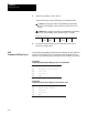
For e xample, assume you have entered a probe tip radius of .01. It is
triggered as axis 2 approaches in the positive direction at the axis 2
coordinate of 1.1200. The value available for paramacro parameter #5072
would be 1.1300
Probe tip radius is defined by the system installer in AMP. This value may
also be changed through the paramacro system parameter #5096, or
through the probe parameter table described in section 27.5.