
Owner's manual

Milling Fixed Cycles
Chapter 26
26-17
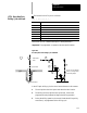
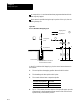
Method I
This shift m ethod is a single axis shift. The direction a nd axis for the
shift is set in AMP by the system installer or can be altered using the
milling fixed cycle parameter table (see section 26.6).
The direction of the axis is specified as + or -.
The feedrate using this shift method is always rapid traverse.
The Q--word shift amount is always interpreted as a positive value.
A negative Q--word is not allowed.
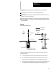
Method II
The direction of the shift using this method is programmed in the
boring c ycle block. Program a shift amount for axes in the current
plane only (determined by G17, G18, or G19) using the following
words:
I__ programs a X axis move.
J__ programs a Y axis move.
K__ programs a Z axis move.
Follow t he I--, J-- and K--words (modal during milling fixed cycles)
with incremental values in the block that programs the hole position.
When using Method II, remember:
If both axes in the current plane are to be shifted, specify both
words t o move the axes.
The move generated will be a single linear move and will execute
at rapid traverse.
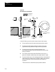
6. The boring tool is then retracted at a rapid feedrate to the initial point
level as determined by G98.
7. After reaching the initial point level, the boring tool is shifted back
(in a manner previously explained and illustrated) and the spindle is
re-started in the counterclockwise direction again.
When the single block function is active, the control stops axis motion
after steps 1, 2 and 8.