
Owner's manual

Milling Fixed Cycles
Chapter 26
26-10
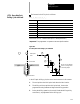
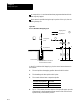
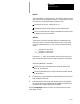
4. If a value was programmed for the P parameter, the drilling tool will
dwell after it reaches the bottom of the hole.
5. It then retracts by an amount d at a rapid feedrate. The amount d is
specified by the system installer, or can be set by the operator as
described in section 26.5. This intermittent feed simplifies chip
disposal and lets a small retraction amount to be set in peck drilling.
6. After the drilling tool retracts an amount d, it then resumes drilling at
the cutting feedrate to a depth d + Q.
This retraction and extension continues until the drilling tool reaches
the depth of the hole as programmed with the Z--word in the drilling
cycle block.
7. The drilling tool then retracts at a rapid feedrate to the initial point
level as determined by G98.
When the single block function is active, the control stops axis motion and
awaits “cycle start”after steps 1, 2 and 7.
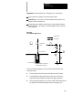
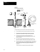
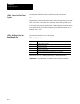
This cycle is used to cut left-handed threads.
CAUTION: The programmer or operator must
set the direction
of spindle rotation for tap-in. The control forces the proper
spindle direction for the tap-out, but uses the programmed
spindle direction for the tap-in.
The format for the G74 cycle is as follows:
G74X__Y__Z__R__P__F__L__;
Where : Is :
X,Y
specifiesthelocation ofthe holeposition intheselected plane.
Z
defines the holebottom.
R
defines the Rpointlevel.
P
defines the dwell period atholebottom.
F
defines the tapping feedrate. Thisshouldbe programmed ascloseas possible
to the rate inwhichthetap willbemovingintothe part(calculated fromthe tap
thread pitchand the active spindle speed). Enterthe feedrate ineither IPMor
IPR modes. No special spindle synchronization occurs with this cycle.
L
defines the numberoftimesthe millingfixedcycle isrepeated.
(See section 26.3 for a detailed description of these parameters.)
(G74):Left-Hand Tapping
Cycle