
Owner's manual

Cutter Diameter Compensation
(G40, G41, G42)
Chapter 21
21-16
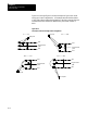
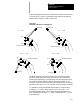
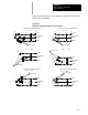
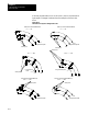
Figure 21.12 through Figure 21.16 show examples of typical exit moves
using type A c utter compensation. All examples assume that the number
of non-motion blocks before the designation of the G40 command have not
exceeded the number allowed as determined by the system installer in
AMP.
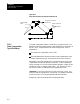
Figure 21.12
Tool Path for Exit Move Straight Line-to-Straight Line
0 •••90
End-point
G42
Programmed
path
G41
G42
Programmed
path
G41
G42
Programmed
path
G41
G42
Programmed
path
G41
End-point
90
•••180
180
•••270 270 •••360
•
•
•
•
r
r
r
r
r
r
r
End-point
End-point
r