
Owner's manual


Cutter Diameter Compensation
(G40, G41, G42)
Chapter 21
21-5
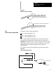
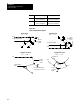
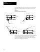
Example 21.2
Cutter Compensation Sample Paths
All of the following blocks result in the same tool path. Assume the
selected plane is the XY plane.
N1D1X0Y0;
N2G41X1Y1;
N3X2;
M30;
or
N1X0Y0F500;
N2G41X1Y1D1;
N3X2;
M30;
or
N1X0Y0F500;
N2G41;
N3X1Y1D1;
N4X2
M30;
Important: The c utter compensation feature is not available for any
motion blocks that are programmed in MDI mode (see section 21.6.5).
The cutter c ompensation mode may be altered by programming either G41,
G42, or G40; or the tool radius may be changed in an MDI program.
However, none of the tool paths executed in MDI is compensated. Any
changes made t o cutter compensation are applied until the next block
executed in automatic mode.
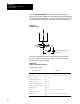
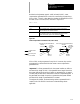
The D--word calls the following data from the offset tables:
initial c utter radius data
cutter radius wear offset data
The sum of these t wo types of offset data is used by the control as the data
for the cutter compensation function.