
Owner's manual


Cutter Diameter Compensation
(G40, G41, G42)
Chapter 21
21-4
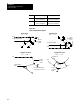
Program the cutter c ompensation function with the following format:
G41(or G42)X ___ Y ___ Z ___ D ___ ;
Where : Is :
G41(or G42)
cuttercompensationdirection,G41=left,G42=right
X, Y, Z
End-pointofentry move into cuttercompensation. Program anentry
moveon axes onlyinthecurrentlyactive plane. Axis motionmust
take placein orderforcuttercompensation to beactive on an axis.
D
Designates theoffsetnumbersand pulls data:1) from the wearand
geometrytables forthetoolradius,and 2)fromthegeometrytable for
tool orientation (see section20.2.1 forinformation onprogramming a
Dword). The Dword isoptional intheG41 orG42 blocks. The D
word mayalsobe designated in anypreviousorfollowingprogram
block.
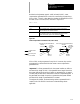
Cutter compensation can be programmed in various ways. Following are
examples of 1-, 2-, and 3-block programs activating cutter compensation
with entry moves.
Example 21.1
Initializing Cutter Compensation
Assume: G17 (XY Plane Selection)
Program Block Comment
One Block
G42 D1 X1 Y1;
Sets compensation right, selects tool
radius offset number, and activates move to
X1 Y1
Two Blocks
D1; Selects tool radius offset number
G42 X1 Y1; Sets compensation right and activates move
to X1 Y1
Three Blocks
D1;
Selects tool radius offset number
G42;
Sets compensation right
X1 Y1;
Activates move to X1 Y1
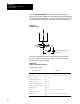
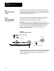
Important: Any entry move (see section 21.3.1 or 21.4.1) into cutter
compensation must be a linear move. Initial activation of cutter
compensation by programming of either the G41 or G42 commands in a
circular cutting mode (G02 or G03) is not allowed. However, if cutter
compensation is already active, the G41 or G42 commands may be
programmed in a circular block to change cutter compensation direction
either left (G41) or right (G42).