
Owner's manual

Chapter
1
6
16-1
Using Chamfers and Corner Radius
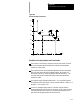
This describes how to use chamfer and corner radius to create corners. A
chamfer is a linear transition between blocks. A corner radius is an arc
transition between blocks.
For cornering you can use either a chamfer or a corner radius between two
motion blocks.
Both the chamfer and the corner radius features are generated between two
motion blocks which must be programmed in the same plane. The motion
block with the chamfer (,C) or the corner radius (,R) word is defined as the
first cornering block. The next motion block in the cornering plane is
defined a s the second block.
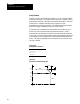
,C Chamfersize - Thisword isused to define a chamferlength thatconnectstwo
intersecting toolpaths. This worddeterminesthedistance thatthechamferwill
beginand endfrom the toolpathsintersection.
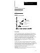
,R Cornerradius - This word isusedtodefinetheradiusofanarcthatistangentto
two intersectingtoolpaths.
If more than one ,C or ,R word is programmed in the same block, only the
right-most word is used, other is ignored. The second block can also have
a chamfer or corner radius word in it. If it does, the second block will also
be used as the first block of the next chamfer or corner radius.
CAUTION: If a programming error of some type is made in the
block defining the second tool path in the chamfer or radius
blocks, the control will not be able to cut t he correct chamfer or
radius. Instead the first block will be executed t o its
programmed end-point. This may cause damage to the part or
cutting tool.
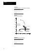
The control will generate an error if t here are more than four non-motion
blocks between the first and second motion blocks defining the corner
transition. A non-motion block is any block that does not generate axis
motion in the currently active plane.
You can use chamfers and corner radius with QuickPath Plus. They may
be programmed in either absolute (G90) or incremental (G91) modes.
16.0
Chapter Overview
16.1
Chamfers and Corner
Radius