
Owner's manual

Using QuickPath Plus
Chapter 15
15-3
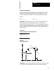
One-end coordinate
Many times part drawings will only give a programmer one--axis
dimension for a tool path and require that the other axis dimension be
calculated by the angle. The following QPP feature eliminates the need for
this calculation. This must be a linear block (see section 15.3 for circular).
The format for this block is as follows:
,A__ {X__};
Y__
Where : Is :
,A
Angle-This word is always displayed asby the control evenifthe angleis
nameddifferentlyin AMP.Ifyou havea 9/240 programthatusesadifferent
address than ,A andyou want torun theprogramona 9/230,9/260or9/290
controltheangles willworkbutthecontrolnamesthem,A.
X,Y
EndPoint-Thiswordisused to programone ofthe coordinates ofthe endpoint
ofa linearpath. The controlwillcalculatetheotherendpointautomatically. T his
canbe anyaxiswordthatisinthecurrentplane.
Only one axes word from the current plane may be programmed in this
block. Any axis word that is not in the current plane will be executed as a
normal linear move to that coordinate and combined with the QPP
generated tool path.
If both axis words from the current plane are entered in the block, the angle
is ignored and the control moves to the coordinate position programmed
with the axis words. All examples in this section will assume the XY
plane is active.
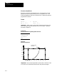
Important: If the programmed tool path is going to be parallel to an axis
in the c urrent plane, the axis word for the end point in the block should be
for the axis in the current plane that is parallel to the tool path. This means
if the value of the angle (,A word) is 0 or 180 degrees the second axis in
the plane must be programmed in the block. If the value of the angle is 90
or 270 degrees the first axis in the plane must be programmed in the block.
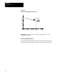
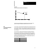
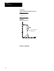
Example 15.1
Angle Designation
N10 GO0 X25 Y0 F100.;
N20 G01 Y15 ,A90;
N30 X5.,A165;
N40 M30;
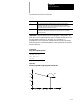
15.2
Linear QuickPathPlus