
Owner's manual

Axis Motion
Chapter 14
14-11
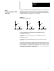
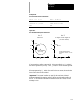
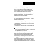
Figure 14.8
Helical Interpolation Direction
Y
G17 G18 G19
G03
G02
G03
G02
G03
G02
XZ
XZY
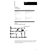
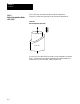
Helical Interpolation in the XY Plane with the Z axis normal.
G17{G02} X__ Y__ Z__ {I__ J__} F__ ;
G03 R__
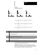
Helical Interpolation in the XZ Plane with the Y axis normal.
G18{G02} X__ Z__ Y__ {I__ K__} F__ ;
G03 R__
Helical Interpolation in the YZ Plane with the X axis normal.
G19{G02} Y__ Z__ X__ {J__ K__} F__ ;
G03 R__
Where : Is :
X, Y, Z
In absolute (G90) mode these are the coordinate valuesofthe endpoint. Inincremental (G91) mode these are the positionsof
the end pointin reference to the startpoint
The axis which isnormal to the circularinterpolation plane produces the “lead”ofthe helix. Again,all axesstartandstopatthe
sametimetoproducehelixmotion.
I, J, K
These determine the position ofthe helixcenter in reference to the startpoint. Thesevaluesare always incremental,regardless
ofthe establishedpositioning mode (absoluteorincremental)
R
Rather thandefininga centerwith I,J,K,the optionexists to define anarcradiususingR. Thesign of thisentry determines the
arccenterpointlocation. IfRisprogrammedas a positive value,thecenterpointwill belocated suchthatanarclessthan180o
isgenerated. IfRisprogrammedas anegative value,the centerpointwillbe locatedsuch thatan arc greaterthan 180• is
generated. RefertoFigure14.5 foranexample.
F
Anotheroptionistoenterafeedratetangentto the tool path. Ifomitted the controlwilluse the feedrate activepriorto this block.
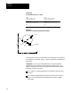
In helical interpolation, the feedrate is the same as in circular interpolation,
that is, the feedrate is tangent to the tool path.
Important: Cutter diameter compensation is effective only for the arc
portion of helical interpolation. Tool length offsets may be active during a
helical move, however, changes to t he tool length offset are allowed only if
it does not affect either of the two circular axes in the move.