
Owner's manual

Coordinate Control
Chapter 13
13-11
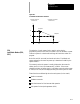
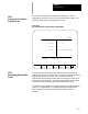
The control has a number of features that operate in specific planes. For
that reason it is frequently necessary to change the active plane using a
G17, G18, or G19.
Some of the features that are plane dependant are:
Circular interpolation
Cutter compensation
Work Coordinate system rotation
Many fixed cycle operations
Important: The system installer determines the planes defined by G17,
G18, and G19 in AMP. Axes may not be assigned to the planes exactly as
listed below. Refer to the documentation prepared by the system installer.
Typical axis names and their corresponding plane assignment are shown
below:
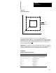
G17 -- plane defined by the X and Y axes (or axes parallel to X and Y)
G18 -- plane defined by the Z and X axes (or axes parallel to Z and X)
G19 -- plane defined by the Y and Z axes (or axes parallel to Y and Z)
Planes can be altered to accommodate additional axes parallel to the
principle axes by programming those a xes in the G17, G18, or G19 block.
See Example 13.4.
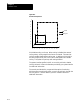
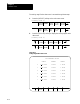
Example 13.4
Altering Planes f or Parallel Axes
Assuming the systeminstaller has madethe fo llowing assignmentsin AMP:
G17 -- the XY plane.
U axis -- parallel to X axis
V axis -- parallel to Y axis
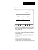
Program block Plane selected Axis Motion
G17;
selects XY plane None
G17 U0;
selectsUY plane U axis moves to zero
G17 V0;
selectsXV plane Vaxis movesto zero
G17 U0V0;
selectsUV plane U&Vaxesmovetozero
13.2
Plane Selection (G17, G18,
G19)