
Owner's manual

Basic Control Operation
Chapter 2
2
-
1
2
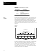
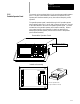
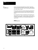
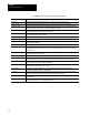
Figure 2.3 shows the push-button MTB panel. Table 2.D explains the
functions of the switches and buttons on the MTB panel. Other optional or
custom MTB panels may be used. Refer to the documentation prepared by
your system installer for details.
We show button names found on the push--button MTB panel between the
< > symbols throughout this manual. The push-button MTB panel uses
defaults when you turn on power to the control. Table 2.D contains these
defaults.
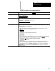
Most of the switches or buttons on the MTB panel are configured by your
system installer’s PAL program. We assume that PAL has been written as
intended for normal operation. If a switch or button does not work the way
it is described in this manual, refer to documentation prepared by your
system installer.
Figure 2.3
Push-Button MTB Panel
19930
JOG SELECT
SPINDLE SPEED
OVERRIDE
SPINDLE
MODE SELECT SPEED/MULTIPLY
RAPID FEEDRATE
OVERRIDE
0
50 100
AUTO MDI MAN
INCR
CONT
HAND HOME
CYCLE
START
SINGLE
BLOCK
CYCLE
STOP
+X +4 --X
+Y TRVRS --Y
+Z --4 --Z
F1
F2
F3 F4
F5 F6
CCW CW
OFF
F1 25
50 100
LOW
X1
MEDL
X10
MED
X100
MEDH
X1000
HIGH
X10000
%
ESTOP
RESET
OFF
ON
AXIS
FUNCTION
FEEDRATE
OVERRIDE
50 120
150
2.2
The MTB Panel