
Owner's manual

Coordinate Control
Chapter 13
13-3
Example 13.1
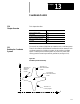
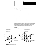
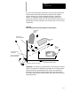
Rotating the Active Work Coordinate System (G68)
These program blocks cause the rotation of the active work coordinate
system as shown in Figure 13.2.
ABSOLUTE PROGRAM INCREMENTAL PROGRAM
N1 G54 G17 G00; N1 G54 G17 G90;
N2 G90 X0. Y0. F500; N2 G00 X0. Y0.;
/N3 G68 X10 Y10 R45; /N3 G68 X10 Y10 R45;
N4 G90 G00 X5. Y5.; N4 G91 G00 X5. Y5.;
N5 G01 X15. F100; N5 G01 X10 F100;
N6 Y15.; N6 Y10;
N7 X5.; N7 X -10;
N8 Y5.; N8 Y -10;
N9 M30; N9 G69;
N10 M30;G54 G00;
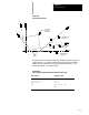
If optional block delete 1 is set “ON”, the control will cut the part shown
with a dashed line in Figure 13.2. If optional block 1 is set “OFF”the
control will cut the part shown with a solid line in Figure 13.2.
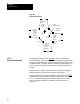
Figure 13.2
Results of Example 13.1
Initial G54 X-axis
unrotated G54 coordinatesystem
rotated G54 coordinatesystem
Initial G54 X-axis
Initial G54 Y-axis Initial G54 Y-axis
Absolute Program Incremental Program
15
10
5
515
Rotated
G54 X-axis
Rotated
G54 X-axis
51510
15
10
5
45
•
45•
15
10
5
15
10
5
Rotated G54 Y-axis