
Owner's manual

Coordinate System Offsets
Chapter 11
11-8
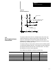
Where :
Is :
L2
tellsthe control th atyou wantto alterthecoordinatesystemtables.
P
specifies whichcoordinate system(G54throughG59.3)youwantto workon. P1
through P9 correspond to the work coordinatesystems G54through G59.3.
P1 = G54 workco ord.system P6 = G59 workcoord.system
P2 = G55 workcoord.system P7 = G59.1workco ord.system
P3 = G56 workcoord.system P8 = G59.2workco ord.system
P4 = G57 workcoord.system P9 = G59.3workco ord.system
P5 = G58 workco ord.system
X_Y_Z_
specifythe locationo f the zero pointofthe specifiedwork coordinatesystem
relativetomachine coordinate system.
Important: G10 blocks may not be programmed when TTRC is active.
Incremental/A bsolute Mode and the G10L2 C ommand
When you program in incremental mode (G91), any values entered into
the work c oordinate system table using the G10 command are added to the
currently active work coordinate system values. When you program in
absolute mode (G90), any values entered into the work coordinate system
table using the G10 command replace the currently active work coordinate
system values.
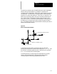
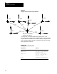
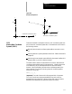
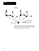
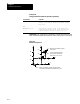
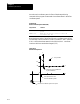
Example 11.3 and Figure 11.7 illustrate how the work coordinate system is
shifted using G10.
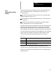
Example 11.3
Work Coordinate System Shift Using G10
Program block WorkCoordinate
Position
Absolute Coordinate
Position
G54X25.Y25.; X25 Y25 X50 Y45
G91;
G10L2P1X10.Y10.;
X15 Y15 X50 Y45
G90;
G10L2P1X3O.Y35.;
X15 Y15 X50 Y45
Important: This modification is permanent. The new table values for the
work coordinate systems are saved even when the control power is turned
off.