
Owner's manual


Introduction to Programming
Chapter 10
10-18
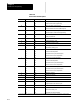
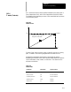
Table 10.A shows the effects of leading zero suppression (LZS)and
trailing zero suppression (TZS
). It presumes that the system installer has
set a format of X5.2 (integer 5 digits, decimal 2 digits) in AMP. Different
formats would result in different decimal point placement compared to
those shown on the following page, but the e nd result would be
comparable.
Table 10.A
How The Control Inter prets Numeric Values
Position Interpreted bythecontrol
ProgrammedX Value TZSDisabled
LZSDisabled
TZSDisabled
LZSEnabled
TZSEnabled
LZSDisabled
X123456. ERROR ERROR ERROR
X12345.6 12345.60 12345.60 12345.60
X1234.56 1234.56 1234.56 1234.56
X123.456 123.45 123.45 123.45
X12345 12345.00 123.45 12345.00
X012345 ERROR 123.45 1234.50
X123456 ERROR 1234.56 12345.60
X1234567 ERROR 12345.67 12345.67
X12345678 ERROR ERROR ERROR
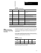
Using LZS and TZS with G-Codes
The following table illustrates how the control interprets different G-Codes
in leading zero and trailing zero suppression modes.
Leading Zero Suppression Mode
(decimalassumed at end ifnot programmed)
T railing Zero Suppression Mode
(2-digitG-codeassumed unlessdecimalpointprogrammed )
Program this: Results in this: Program this: Results in this:
G02 2 G02 2
G2 2 G2 20
G2. 2 G2. 2
G92 92 G92 92
G920 920 G920 920 or92 (ifno AMPdefinedmacro 920)
G92.1 92.1 G92.1 92.1