
Owner manual

Chapter 11
Coordinate Control
11-33
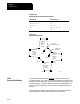
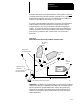
The control has a number of feat ures that operate in specific planes. For
that reason, it is frequently necessary to change the active plane using a
G17, G18, or G19 code.
This is especially true for surface grinding machines. Cylindrical grinders
are generally limited to using the G18 plane only.
Some of the features that are plane dependant are:
Circular interpolation
Dresser/wheel radius compensation
Most fixed cycle operations
Important: Your system installer determines the axis names, axis
integrands, and parallel axes for each plane in AMP. Your system may not
have planes assigned exactly as listed below. See the documentation
prepared by your system installer.
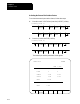
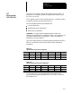
Typical axis names and their corresponding plane assignment are shown in
Table 12.A and Table 12.B (this manual assumes these configuration
throughout):
Table 12.A
Typical Surface Grinder Plane Configuration
PLANE 1stAxis 2n d Axis 1st Integrand 2nd Integrand 1st Parallel 2nd Parallel
G17 X Y I J U V
G18 Z X K I W U
G19 Y Z J K V W
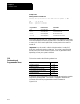
Table 12.B
Typical Cylindrical Grinder Plane Configuration
PLANE 1st Axis 2nd Axis 1stIntegran d 2nd Integrand 1st Parallel 2nd Parallel
G17 none none none none none none
G18 Z X K I W U
G19 none none none none none none
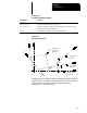
You can alter planes to accommodate additional axes parallel t o the
principle axes by programming those axes in a G17, G18, or G19 block.
See Example 11.13.
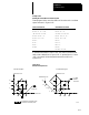
11.7
Plane Selection
(G17,G18, G19)