Allen-Bradley 9/Series CNC Grinder Operation and Programming Manual
Important User Information Because of the variety of uses for the products described in this publication, those responsible for the application and use of this control equipment must satisfy themselves that all necessary steps have been taken to assure that each application and use meets all performance and safety requirements, including any applicable laws, regulations, codes and standards.
9/Series Grinder Operation and Programming Manual October 2000 Summary of Changes New Information The following is a list of the larger changes made to this manual since its last printing. Other less significant changes were also made throughout. Error Message Log Paramacro Parameters Softkey Tree Error Messages Revision Bars We use revision bars to call your attention to new or revised information. A revision bar appears as a thick black line on the outside edge of the page as indicated here.
Chapter 1-2
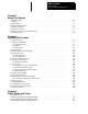
Table of Contents Index (General) 9/Series Grinder 9/Series PAL Reference Manual Operation and Programming Manual Chapter 1 Using This Manual 1.0 Chapter Overview . . . . . . . . . . . . . . . . . . . . . . . . . . . . . . . . . . . . . . . . . . . . . . . . . . . . . . . . . . . . . . . . . 1.1 Audience . . . . . . . . . . . . . . . . . . . . . . . . . . . . . . . . . . . . . . . . . . . . . . . . . . . . . . . . . . . . . . . . . . . . . . . 1.2 Manual Design . . . . . . . . . . . . . . . . . . . . . .
TableIndex of Contents (General) Grinder 9/Series PAL9/Series Reference Manual Operation and Programming Manual 3.3.1 Dresser Orientations . . . . . . . . . . . . . . . . . . . . . . . . . . . . . . . . . . . . . . . . . . . . . . . . . . . . . . . . . . . 3.3.2 Grinding Wheel Orientations . . . . . . . . . . . . . . . . . . . . . . . . . . . . . . . . . . . . . . . . . . . . . . . . . . . . . 3.4 Entering Offset Data {WHEEL GEOMET} or {RADIUS TABLE} . . . . . . . . . . . . . . . . . . . . . . . . . . . .
Table of Contents Index (General) 9/Series Grinder 9/Series PAL Reference Manual Operation and Programming Manual 5.4.1 Linear Digitizing . . . . . . . . . . . . . . . . . . . . . . . . . . . . . . . . . . . . . . . . . . . . . . . . . . . . . . . . . . . . . . 5.4.2 Digitizing an Arc (3 Points) . . . . . . . . . . . . . . . . . . . . . . . . . . . . . . . . . . . . . . . . . . . . . . . . . . . . . . . 5.4.3 Digitizing An Arc Tangent at End Points . . . . . . . . . . . . . . . . . . . . . . . . . . . . .
TableIndex of Contents (General) Grinder 9/Series PAL9/Series Reference Manual Operation and Programming Manual Chapter 8 Display and Graphics 8.0 Chapter Overview . . . . . . . . . . . . . . . . . . . . . . . . . . . . . . . . . . . . . . . . . . . . . . . . . . . . . . . . . . . . . . . . . 8.1 Selection of Axis Position Data Display . . . . . . . . . . . . . . . . . . . . . . . . . . . . . . . . . . . . . . . . . . . . . . . . . . 8.2 PAL Display Page . . . . . . . . . . . . . . . . . . . . . . . . . .
Table of Contents Index (General) 9/Series Grinder 9/Series PAL Reference Manual Operation and Programming Manual 10.5.2 A_L_,R_,C_ (QuickPath Plus Words) . . . . . . . . . . . . . . . . . . . . . . . . . . . . . . . . . . . . . . . . . . . . . . 10.5.3 F Words (Feedrate) . . . . . . . . . . . . . . . . . . . . . . . . . . . . . . . . . . . . . . . . . . . . . . . . . . . . . . . . . . . 10.5.4 G Words (Preparatory Functions) . . . . . . . . . . . . . . . . . . . . . . . . . . . . . . . . . . . . . . . .
TableIndex of Contents (General) Grinder 9/Series PAL9/Series Reference Manual Operation and Programming Manual Chapter 12 Axis Motion 12.0 Chapter Overview . . . . . . . . . . . . . . . . . . . . . . . . . . . . . . . . . . . . . . . . . . . . . . . . . . . . . . . . . . . . . . . . 12.1 Positioning Axes . . . . . . . . . . . . . . . . . . . . . . . . . . . . . . . . . . . . . . . . . . . . . . . . . . . . . . . . . . . . . . . . . 12.1.1 Rapid Positioning Mode (G00) . . . . . . . . . . . . . . . . . . .
Table of Contents Index (General) 9/Series Grinder 9/Series PAL Reference Manual Operation and Programming Manual 12.9.7 Controlling Spindles (G12.1, G12.2, G12.3) . . . . . . . . . . . . . . . . . . . . . . . . . . . . . . . . . . . . . . . . . . 12.9.8 Spindle Orientation (M19, M19.2, M19.3) . . . . . . . . . . . . . . . . . . . . . . . . . . . . . . . . . . . . . . . . . . . 12.9.9 Spindle Direction (M03, M04, M05) . . . . . . . . . . . . . . . . . . . . . . . . . . . . . . . . . . . . . . . . . . . .
TableIndex of Contents (General) Grinder 9/Series PAL9/Series Reference Manual Operation and Programming Manual 15.4 Type A Compensation Paths . . . . . . . . . . . . . . . . . . . . . . . . . . . . . . . . . . . . . . . . . . . . . . . . . . . . . . . . . 15.4.1 Type A Compensation Entry Moves . . . . . . . . . . . . . . . . . . . . . . . . . . . . . . . . . . . . . . . . . . . . . . . 15.4.2 Type A Compensation Exit Moves . . . . . . . . . . . . . . . . . . . . . . . . . . . . . . . . . . . . . . . . .
Table of Contents Index (General) 9/Series Grinder 9/Series PAL Reference Manual Operation and Programming Manual Chapter 18 Turning Operations 18.0 Chapter Overview . . . . . . . . . . . . . . . . . . . . . . . . . . . . . . . . . . . . . . . . . . . . . . . . . . . . . . . . . . . . . . . . 18.1 Single Pass Turning Cycles . . . . . . . . . . . . . . . . . . . . . . . . . . . . . . . . . . . . . . . . . . . . . . . . . . . . . . . . . 18.1.1 Single Pass O.D. and I.D. Roughing Cycle (G20) . . . . . . . .
TableIndex of Contents (General) Grinder 9/Series PAL9/Series Reference Manual Operation and Programming Manual Chapter 21 In-process Dresser 21.0 Chapter Overview . . . . . . . . . . . . . . . . . . . . . . . . . . . . . . . . . . . . . . . . . . . . . . . . . . . . . . . . . . . . . . . . 21.1 Offset Generation While Dressing . . . . . . . . . . . . . . . . . . . . . . . . . . . . . . . . . . . . . . . . . . . . . . . . . . . . . 21.1.1 Plane Selection for the In-process Dresser Offset . . . . . . . . .
Chapter 1 Using This Manual 1.0 Chapter Overview This chapter describes how to use this manual. Major topics include: how the manual is written and what fundamentals are presumed to be understood by the reader how the manual is organized and what information can be found in it definitions for certain key terms 1.1 Audience We wrote this manual for operators and programmers who use Allen-Bradley controls. We assume that you are familiar with the basic operation and programming of a CNC. 1.
Chapter 1 Using This Manual 1.3 What This Manual Contains Chapter 1-2 This table contains a brief summary of each chapter. Title Summary 1 Manual Overview Manual overview, intended audience, definition of key terms, how to proceed. 2 Operating the Control A brief description of the control’s basic operation including power-up, MTB panel, operator panel, access control, and E-STOP. 3 Offset Tables and Setup Basic setup of the offset table, other initial operating parameters.
Chapter 1 Using This Manual 1.4 Reading This Manual To make this manual easier to understand, we included these explanations of terms and symbols: All explanations, illustrations, and charts presented are based on standard CNC functions. Operations can differ from the basic information provided in this manual depending on the configuration of your grinder machine controlled by the CNC. For details, see the manuals prepared and supplied by your system installer.
Chapter 1 Using This Manual 1.5 Terms and Conventions To make this manual easier to read and understand, we shortened the full product names and features. Shortened terms include: Term 1.
Chapter 1 Using This Manual 1.7 Related Publications For more information about Allen-Bradley controls, see these publications: Pub. No. Document Name 8520-4.3 9/Series CNC PAL Reference Manual 8520-- 5.1.1 9/Series CNC Lathe Operation and Programming Manual 8520-- 5.1.3 9/Series CNC Mill Operation and Programming Manual 8520-- 5.1.4 9/Series CNC Grinder Operation and Programming Manual 8520-5.1.5 9/Series Data Highway Plus Communication Module User Manual 8520-5.1.
Chapter 1 Using This Manual 1-6
Chapter 2 Operating the Control 2.0 Chapter Overview This chapter covers the basics necessary for operation of the Allen-Bradley 9/Series control.
Chapter 2 Operating the Control 2.1 Operator Panel Operations Use the operator panel to: display a part program display control status and wheel position edit a part program display and enter wheel offset data display the status of input/output signals display and enter programmable zone boundaries set the level of protection for: - part programs - wheel offset data - AMP data You can perform other operations by using the operator panel. They are covered in the remaining chapters of this manual. Figure 2.
Chapter 2 Operating the Control Figure 2.2 shows the color operator panel. It has keys and softkeys identical to the monochrome operator panel in a slightly different configuration. Figure 2.2 Color Operator Panel 9/SERIES 7 8 9 4 5 6 1 2 3 0 : + _ N O . D F X Z Y # L A B C S T , & EOB DEL CAN RES ) LINE ( CNTRL DISP PROC TRANSMIT SP W V H ? E U = G P Q R M CALC I J K SHIFT [ ] 19436 2.1.1 Using the Keyboard Table 2.
Chapter 2 Operating the Control Table 2.A Key Functions 2-4 Key Name Function Address and Numeric Keys Use these keys to enter alphabetic and numeric characters. If a key has two characters printed on it, pressing it normally enters the upper left character. Holding down the [SHIFT] key while pressing it enters the lower right character. Cursor Keys ←, ↑, →, ↓ Use these keys to move the cursor left, right, up and down in the data display area (lines 4-21) of the screen.
Chapter 2 Operating the Control 2.1.2 Softkeys You access the various software features and functions of the control through softkeys. Softkeys are the row of 7 keys located at the bottom of the CRT as shown in Figure 2.3. They let you move through the control’s software. The control displays the function of each softkey on the CRT directly above the softkey. In this manual, softkey names appear between the { } symbols. Figure 2.
Chapter 2 Operating the Control Use the exit softkey {↑} (on the far left) to regress softkey levels. For example, if you are currently on softkey level 3 and you press the exit softkey, the softkeys change to the softkeys previously displayed on softkey level 2. When you press the exit softkey while holding down the [SHIFT] key, the softkey display returns to softkey level 1 regardless of the current softkey level.
Chapter 2 Operating the Control 2.1.3 Using the CRT Your control has one of these monitors: 9-inch monochrome monitor 19435 12-inch color monitor 19436 Both have identical displays and graphics capabilities.
Chapter 2 Operating the Control 2.2 The MTB Panel Figure 2.4 shows the MTB panel. Table 2.B lists the selections on this panel. Your system may contain optional or custom MTB panels different than the one shown below. See the documentation prepared by your system installer for details. We show selection names on the MTB panel between the < > symbols when referred to in this manual. Most selections on the MTB panel are configured by your system installer’s PAL program.
Chapter 2 Operating the Control Table 2.
Chapter 2 Operating the Control Table 2.B Selections on the MTB Panel and How They Work (continued) Switch or Button Name How It Works = Default for Push-Button MTB Panel SPINDLE SPEED OVERRIDE Selects the override for programmed spindle speeds in 5% increments within a range of 50% to 120%. SPINDLE or SPINDLE DIRECTION Selects spindle rotation, clockwise (CW), spindle stop (OFF), counterclockwise (CCW). Can be overridden by any programmed spindle direction command.
Chapter 2 Operating the Control 2.3 Software MTB Panel {FRONT PANEL} The 9/Series control offers a software MTB panel that performs many of the functions of an MTB panel. This feature uses softkeys instead of the normal switches and buttons of a panel. If your control uses a standard MTB panel (described on page 2-8) or some other custom MTB panel, the requests for operations from the panel take priority.
Chapter 2 Operating the Control The software MTB panel controls these features: (continued) Feature Function Jog the Axes Allows manual motions to be performed in any one of the jogging modes. You cannot perform multi-axis jogs using the software front panel feature. See page 4-2 for details. Set Zero Changes the wheel’s current position in the work coordinate system to 0 for the selected axis. This is done by shifting the work coordinate system. See page 12-89 for details.
Chapter 2 Operating the Control SOFTWARE FRONT PANEL MODE SELECT: RAPID TRAVERSE: FEEDRATE OVR: RAPID FEEDRATE OVR: SPINDLE DIRECTION: SPINDLE SPEED OVR: DRY RUN MODE: BLOCK DELETE: M-FUNC LOCK: OPTIONAL STOP: SINGLE BLOCK: MIRROR IMAGE: AXIS INHIBIT: MDI OFF 0% 0% OFF 50% OFF OFF OFF OFF OFF X XZ USE CURSOR FOR SELECTION JOG AXIS PRGRAM EXEC 2. Press the up and down cursor keys to select the feature to change. The value of the selected feature appears in reverse video. 3.
Chapter 2 Operating the Control Jog Axis Screen After accessing the software front panel screen and selecting the various features for your application, you can use the jog axis screen to: jog the axes of the control shift the current work coordinate system to force the current wheel position to be the zero point of the work coordinate system To jog the axes of the control: 1. Press the {JOG AXIS} softkey. The {JOG AXIS} softkey is only available when mirror image or axis inhibit are not in reverse video.
Chapter 2 Operating the Control You can select the: axis to jog type of jog speed multiply value (see manual operating mode on page 4-1) HPG number (if HPG has been selected as the type of jog) 2. Use the up and down cursor keys to select a parameter and the left and right cursor keys to alter the value assigned to that parameter. 3.
Chapter 2 Operating the Control To perform one of these options: 1. Press the {PRGRAM EXEC} softkey. (softkey level 2) JOG AXIS PRGRAM EXEC You see the program execute screen: E-STOP PROGRAM [ MM ] F 0.000 MMPM 0.0 R X 0.000 S Z 0.
Chapter 2 Operating the Control 2. Press the softkey that corresponds to the selected option. To perform this operation: Press: Cycle Start or Cycle Stop the softkey that corresponds to the desired feature. Details on these features are described earlier in this chapter. Block Retrace the {BLOCK RETRCE} softkey; each time you press the {BLOCK RETRCE} softkey the control automatically retraces the previously executed block. Pressing {CYCLE START} returns the wheel to the start point of block retrace.
Chapter 2 Operating the Control 2.4 Powering the Control This section describes the procedures for turning on and off power to the control. See the documentation prepared by your system installer for more specific procedures. 2.4.1 Turning On Power Follow this procedure to turn on power to the control: 1. Visually make sure that the control and the machine are in normal operating condition. 2. Press the power button.
Chapter 2 Operating the Control After power has been turned on, the control displays the power turn-on screen. To activate the main menu, press the [TRANSMIT] key. You see the main menu screen: E-STOP PROGRAM [ MM ] F R X 00000.000 S Z 00000.000 T 00000.000 MMPM 12345 FILENAME SUB NAME 9999 MEMORY MDI STOP (PAL messages) PRGRAM OFFSET MACRO MANAGE PARAM PRGRAM SYSTEM CHECK SUPORT The softkeys available on the main menu screen are referred to as “level 1” softkey functions.
Chapter 2 Operating the Control 2.4.2 Turning Off Power Turn off power to the control when it is not used for an extended period of time. To turn off power to the control: ATTENTION: To prevent damage to the machine, never turn off power while a part program is being executed. Before turning off power, make sure that the control is in CYCLE STOP. 2.5 Control Conditions at Power-Up 1. Press the button. 2.
Chapter 2 Operating the Control The control defaults to one G-code from each of these groups (as set in AMP): Modal Group: G-code: 1 G00 G01 Rapid traverse Linear interpolation 2 G17 G18 G19 Plane Selected Plane Selected Plane Selected 3 G90 G91 Absolute Incremental 4 G22 G22.1 G23 G23.
Chapter 2 Operating the Control 2.6 Emergency Stop Operations Press the red button on the MTB panel (or any other E-Stop switches installed on your machine) to stop operations regardless of the condition of the control and the machine. ATTENTION: To avoid damage to equipment or hazard to personnel, your system installer should connect the button so that pressing the button opens the circuit connected to the E-STOP STATUS terminal on the control’s subprocessor board.
Chapter 2 Operating the Control To reset the emergency stop state, press the button. Once you push the E--Stop Reset button to clear the E--Stop state, the message, “RESETTING E--STOP” displays to alert you that the control is attempting to come out of E--Stop. After the cause of the E--Stop is resolved, the control clears the “E--STOP” message.
Chapter 2 Operating the Control protection by assigning a level as the power-up level using the “POWER-UP LEVEL” parameter as described on page 2-29. 2.7.
Chapter 2 Operating the Control {ACCESS CONTRL} function. {ACCESS CONTRL}. 2. Enter a password that has access to Press the {ACCESS CONTRL} softkey. This displays the access control screen (Figure 2.5). (softkey level 2) ACCESS CONTRL Figure 2.
Chapter 2 Operating the Control 3. Press the softkey that corresponds to the access level for which you want to assign access to functions. The pressed softkey appears in reverse video. The password name assigned to that access level is moved to the “PASSWORD NAME.
Chapter 2 Operating the Control Important: If you want to activate or deactivate a function that is not accessible to the current user’s access level, the message “ACCESS TO THIS FUNCTION NOT ALLOWED” appears. Only features that are accessible to the current user’s access level can be selected as accessible or inaccessible to a lower user’s access level. 7. Press the {UPDATE & EXIT} softkey to store the changes made to accessible functions for the user levels and return the control to softkey level 1.
Chapter 2 Operating the Control Table 2.C Password Protectable Functions Parameter Name Function becomes accessible when parameter name appears in reverse video: 1) ACTIVE PROGRAM To access these features, both ACTIVE PROGRAM and PROGRAM MANAGE (number 2 below) must be assigned to the user. • {SELECT PRGRAM} — Select a program for automatic operation. • {SEARCH} — Search a part program for a character string or sequence number to begin program execution at.
Chapter 2 Operating the Control Table 2.C Password Protectable Functions (continued) Parameter Name Function becomes accessible when parameter name appears in reverse video: 15) PRGRAM PARAMETERS {PRGRAM PARAM} — Display and change the tables for programmable zones 1 and 2, the single digit feedrates, and the fixed cycle operating parameters. 16) ONLINE AMP {AMP} — Display and change the online adjustable machine parameters.
Chapter 2 Operating the Control If the {ACCESS CONTRL} softkey does not appear on the screen, the currently active access level is not allowed to use the {ACCESS CONTRL} function. Enter a password that has access to {ACCESS CONTRL}. 2. Press the {ACCESS CONTRL} softkey. This displays the access control screen (Figure 2.5). (softkey level 2) ACCESS CONTRL 3. Press the {STORE BACKUP} softkey.
Chapter 2 Operating the Control To enter a password, follow these steps: 1. Press the {PASSWORD} softkey. (softkey level 1) FRONT PANEL ERROR PASSMESAGE WORD SWITCH LANG You see the password log-on screen: E-STOP ENTER PASSWORD: PROGRAM [INCH] F 0.000 MMPM Z 00000.000 S 0 R X 00000.000 T C 359.99 MEMORY MAN 1 STOP ACCESS CONTRL The prompt “ENTER PASSWORD:” appears on line 2 of the CRT. 2. Enter the password. The control displays only * for the characters entered.
Chapter 2 Operating the Control 2.8 Changing Operating Modes The control provides 3 basic operation modes: Manual (MAN or MANUAL) Manual Data Input (MDI) Automatic (AUTO) You can select a mode by using on the MTB panel, or by using the {FRONT PANEL} softkey. This is configurable by your system installer. Both means of selection may not be available. Details about using the {FRONT PANEL} softkey are given on page 2-11.
Chapter 2 Operating the Control (1) Manual mode To operate the machine manually, select MAN or MANUAL under or press the {FRONT PANEL} softkey. Use the left/right arrow keys to change the mode select options if using {FRONT PANEL}. Details about using the {FRONT PANEL} softkey are given on page 2-11. For details on manual mode operation, see chapter 4. Figure 2.6 Manual Mode Screen E-STOP PROGRAM [ MM ] F 00000.000 R X 00000.000 S Z 00000.
Chapter 2 Operating the Control (2) MDI mode To operate the machine in MDI mode, select MDI under or press the {FRONT PANEL} softkey Use left/right arrow keys to change mode select options if using {FRONT PANEL}. Details about using the {FRONT PANEL} softkey are given on page 2-11. For details on MDI operation, see chapter 4. Figure 2.7 MDI Mode Screen MDI: E-STOP PROGRAM ] F R X 00000.000 S Z 00000.
Chapter 2 Operating the Control (3) Automatic mode To operate the machine automatically, select AUTO under or press the {FRONT PANEL} softkey Use left/right arrow keys to select mode options if using {FRONT PANEL}. Details about using the {FRONT PANEL} softkey are given on page 2-11. For details on automatic operation, see chapter 7. Figure 2.8 Automatic Operation Screen E-STOP PROGRAM ] F R X 00000.000 S Z 00000.
Chapter 2 Operating the Control 2.9 Control and Block Reset Block Reset Use the block reset feature to force the control to skip the execution of a block. To use the block reset function, you must stop program execution. If program execution is stopped: Then: before the control has completely finished the execution of the block a block reset aborts any portion of that block that has not been executed. after the complete execution of a block (as in the case of single-block execution or a M00, etc.
Chapter 2 Operating the Control 2.10 Displaying System and Machine Messages The control has two screens dedicated to displaying messages. The MESSAGE ACTIVE screen displays up to nine of the most current system messages and ten of the most current machine (logic generated) messages at a time. The MESSAGE LOG screen displays a log of up to 99 system messages and a separate log of up to 99 machine messages that occurred since the last time memory was cleared.
Chapter 2 Operating the Control Figure 2.9 Message Active Display Screen MESSAGE ACTIVE SYSTEM MESSAGE (The system error messages are displayed in this area) MACHINE MESSAGE (The logic messages are displayed in this area) ERROR LOG CLEAR ACTIVE This is the information displayed on the MESSAGE ACTIVE screen. The control displays up to 9 active system messages and up to 10 machine messages.
Chapter 2 Operating the Control Figure 2.10 Message Log Display Screen MESSAGE LOG PAGE 1 of 9 SYSTEM MESSAGE (The logged system error messages are displayed in this area) MACHINE MESSAGE (The logged logic messages are displayed in this area) ACTIVE TIME ERRORS STAMPS This is the information displayed on the MESSAGE LOG screen. The control displays up to 99 system messages and up to 99 machine messages.
Chapter 2 Operating the Control 2.10.1 Clearing Active Messages {CLEAR ACTIVE} After the cause of a machine or system message has been resolved, some messages remain displayed on all screens until cleared. ATTENTION: Not clearing the old messages from the screen can prevent messages that are generated later from being displayed. This occurs when the old resolved message is of a higher priority than the newly generated message.
Chapter 2 Operating the Control 2.11 The Input Cursor The input cursor is the cursor located on line 2 and 3 of the screen. It appears when you must input data using the operator panel (as needed in MDI mode, for example). This section describes how to move the cursor and edit data on the input line by using the keys on the operator panel. Moving The Input Cursor To move the cursor left or right in the input area, press and hold the [SHIFT] key while pressing the left or right cursor keys.
Chapter 2 Operating the Control 2.12 {REFORM MEMORY} Sometimes you must perform a reform memory operation on the control to clear memory.
Chapter 2 Operating the Control 2. Press the {REFORM MEMORY} softkey. (softkey level 2) ACTIVE EDIT RESTRT DISPLY COPY PRGRAM PRGRAM PRGRAM PRGRAM PRGRAM DELETE VERIFY PRGRAM RENAME INPUT PRGRAM PRGRAM COMENT PRGRAM DEVICE REFORM CHANGE MEMORY DIR 3. Press the {REFORM YES} softkey. All programs that are stored in control memory are deleted. (softkey level 3) REFORM REFORM YES NO It can take several seconds for the control to complete the operation.
Chapter 2 Operating the Control 2.14 Time Parts Count Display Feature The time parts count display logs data relevant to part program execution, including: number of parts ground cycle time lot size remaining parts You display and alter this data through the time parts screen. Three levels of access are available to the time parts screen. They are listed below in order of most restrictive to least restrictive. See page 2-27 for details on password protection and access control.
Chapter 2 Operating the Control 2. Press the {ACTIVE PRGRAM} softkey. (softkey level 2) ACTIVE EDIT RESTRT DISPLY COPY PRGRAM PRGRAM PRGRAM PRGRAM PRGRAM DELETE VERIFY PRGRAM RENAME INPUT PRGRAM PRGRAM COMENT PRGRAM DEVICE REFORM CHANGE MEMORY DIR 3. Press the {TIME PARTS} softkey. (softkey level 3) DE-ACT SEARCH MID ST T PATH PRGRAM PRGRAM GRAPH SEQ STOP TIME PARTS Figure 2.
Chapter 2 Operating the Control Important: All softkeys appear in Figure 2.11 may not appear on your system due to restricted access. See the beginning of this section and page 2-27 for details. Table 2.D lists the time part screen fields and their definitions. Table 2.D Time Part Screen Field Definitions 2-46 Field: Definition: Program indicates the currently active part program, displayed automatically by the control. Date indicates the current date setting.
Chapter 2 Operating the Control Changing Date To change the date setting: 1. Press the {SET DATE} softkey, provided that you have supervisor-level access. You are prompted for a new date with a line that displays the current date setting. 2. Press the [DEL] key to erase the characters displayed. 3. Type in the new date.
Chapter 2 Operating the Control Clearing/Resetting a Field To clear/reset a field to zero: 1. Press the {ED PRT INFO} softkey, provided that you have supervisor-level access. 2. Press the up and down cursor keys to move to the field you want to clear/reset. 3. Enter a Y or a numeric value at the prompt for this field. 4. Press [TRANSMIT] to accept the change. Press the exit softkey {↑} to return to the “Active Program” screen. 2.
Chapter 2 Operating the Control For the calculator function, 2147483647 (10 characters long) is the largest number that you can enter on the input line. If you see the error message: The number entered or calculated is: “NUMBER IS OUT OF RANGE” too large (longer than 10 characters) “MATH OVERFLOW” greater than 2147483647 Fractional numbers cannot exceed .999999 (6 decimal places). If the number of decimal places is exceeded, the control automatically rounds off based on the seventh digit.
Chapter 2 Operating the Control If you perform the same level of evaluation, the left most operation takes priority. Example 2.1 Mathematic Expressions Expression Entered Result Displayed 12/4*3 9 12/[4*3] 1 12+2/2 13 [12+2]/2 7 12-4+3 11 12-[4+3] 5 Table 2.F contains the function commands available with the [CALC] key. Table 2.
Chapter 2 Operating the Control The control executes functions in Table 2.F from left to right in a program block. These functions are executed before the control executes any mathematical operators such as addition or subtraction. This order of execution can be changed only by enclosing operations in brackets [ ]. Operations enclosed in brackets are executed first. Example 2.
Chapter 2 Operating the Control Paramacro Variables in CALC Operations Any paramacro variable can be accessed through the CALC function. Include a # sign followed by the paramacro variable number. When the calculation is performed the value of that paramacro variable is substituted into the equation. You can not change the value of paramacro variables with the CALC function.
Chapter 3 Offset Tables and Setup 3.0 Chapter Overview This chapter describes the offset tables and their setup. The major topics described in this chapter include: Topic: 3.
Chapter 3 Offset Tables and Setup Figure 3.
Chapter 3 Offset Tables and Setup Important: The first 4 wheel offset numbers (01-04) are reserved for use in conjunction with an in-process dresser. When the in-process dresser is disabled, the control automatically updates these first 4 offset numbers with the current grinding wheel size. These offset values should not be manually entered. See chapter 21 for details on using the in-process dressing feature.
Chapter 3 Offset Tables and Setup Figure 3.2 shows typical length offsets for a cylindrical grinder. Generally grinders are configured such that axes move in the negative direction as they move the wheel towards the workpiece (along -X axis) and towards the chuck (along -Z axis). Assuming this applies to your system, enter a positive Z offset value to offset the gauge point away from the part spindle. Enter a positive X offset value to offset the gauge point away from the part spindle center line.
Chapter 3 Offset Tables and Setup The dresser radius and corner radius compensation schemes use the same radius table to store a radius value. The entire wheel radius scheme stores the entire wheel radius in paramacro variable #5508. Which dresser/wheel radius compensation scheme to use on your system depends on the current application of your grinder. See chapter 15 for details on how to properly implement these schemes.
Chapter 3 Offset Tables and Setup Dresser Radius The control can compensate for errors resulting from slight or even large rounding of the dresser tip. To do so, the radius of the dresser must be entered in the radius table. For more information on activating an offset for dresser/wheel radius compensation, see chapter 15. Figure 3.4 Dresser Radius for a Typical Diamond Point Dresser .
Chapter 3 Offset Tables and Setup Figure 3.5 Corner Radius for a Typical Grinding Wheel .25 Radius .3 Radius X length offset Z length offset Z length offset X length offset 11986-I Entire Wheel Radius The control can compensate for the radius of the entire grinding wheel. To do so, the radius of the wheel must be entered in the radius table for dresser/wheel radius compensation. This method of compensation does not require any X-length offset to be activated.
Chapter 3 Offset Tables and Setup Figure 3.6 Entire Wheel Radius for a Typical Grinding Wheel Radius of Entire Wheel 11987-I 3.3 Dresser/Wheel Orientation {RADIUS TABLE} Orientation of the grinding wheel or diamond point dresser is essential information for dresser/wheel radius compensation to function properly. Orientation data tells the control which side of the dresser/wheel is available for grinding relative to the wheel/part surface.
Chapter 3 Offset Tables and Setup 3.3.1 Dresser Orientations Figure 3.7 shows the possible dresser orientations relative to the grinding wheel. Figure 3.7 Dresser Orientations 4 8 3 7 0 or 9 5 1 6 2 11988-I The control uses the value selected for orientation to determine the orientation of the dresser when dresser/wheel radius compensation is active. Enter the proper dresser orientation number (0-9) in the radius offset table for the ORNT parameters.
Chapter 3 Offset Tables and Setup 3.3.2 Grinding Wheel Orientations Figure 3.8 shows the possible grinding wheel orientations relative to the part surface. The orientation numbers point to the surface of the grinding wheel being used to grind the part. Figure 3.8 Wheel Orientations 2 6 1 5 7 0 or 9 5 7 3 4 8 11989-I The control uses the value selected for orientation to determine the orientation of the grinding wheel when dresser/wheel radius compensation is active.
Chapter 3 Offset Tables and Setup 3.
Chapter 3 Offset Tables and Setup 2. Decide if you want to display: wheel length offset table or radius/orientation offset table (softkey level 2) WORK WHEEL RADIUS DRESSR SCALNG CO-ORD GEOMET TABLE TABLE COORD BACKUP ROTATE OFFSET 3. To display: Press this softkey: wheel length offsets {WHEEL GEOMET} An example of a wheel length offset table screen is shown in Figure 3.9. radius/orientation offsets {RADIUS TABLE} An example of a radius/orientation offset table screen is shown in Figure 3.10.
Chapter 3 Offset Tables and Setup 4. Select data entry type: Unit selection {INCH/METRIC} To select units of “mm” or “inch” for the offset data, press the {INCH/METRIC} softkey. The unit selection changes each time you press the softkey. When you alter the units, the control converts all existing data to the new unit selection for that offset number.
Chapter 3 Offset Tables and Setup 5. Offset data can be replaced or added to: If you want to: Key in the: Press this softkey: replace stored offset data with new data new data {REPLCE VALUE} add to previously stored offset data amount to be added {ADD TO VALUE} You can copy length offset data from one axis to another axis for all offset numbers (rather than having to change each axis individually). a. Press the {COPY OFFSET} softkey. “COPY (SOURCE, DESTINATION) :” appears. b.
Chapter 3 Offset Tables and Setup Figure 3.9 Offset Table Screen for Wheel Length TOOL OFFSET NUMBER: WHEEL GEOMETRY TABLE PAGE 1 OF 7 TOOL # R X Z 1 [INCH] -12345.678 -12345.678 2 [INCH] -12345.678 -12345.678 3 [INCH] -12345.678 -12345.678 TOOL # R X Z 4 [INCH] -12345.678 -12345.678 5 [INCH] -12345.678 -12345.678 6 [INCH] -12345.678 -12345.678 SEARCH REPLCE ADD TO ACTIVE MORE NUMBER VALUE VALUE OFFSET OFFSET Figure 3.
Chapter 3 Offset Tables and Setup 3.5 Set Offset Data Using {MEASURE} The measure feature offers an easy method of establishing wheel length offsets. This feature is not available for generating any radius offset data. The control, not the operator, computes the wheel length offsets, and enters these values in the wheel geometry offset table. You can only perform the measure operation on one axis at a time. To enter wheel length offsets using measure, follow these steps: 1.
Chapter 3 Offset Tables and Setup 3.6 Changing the Active Dresser/Wheel Offset {ACTIVE OFFSET} This feature allows the manual activation of wheel length and radius/orientation offsets without the need to program the correct T word to call the corresponding offset number. Typically you change the wheel length and radius/orientation offsets by programming a T word as described in chapter 13. Use this feature only when you need to activate one of these offset numbers manually.
Chapter 3 Offset Tables and Setup 4. Press the {ACTIVE OFFSET} softkey when the offset you want is selected. Length offsets are made active as described in chapter 13. Radius/orientation offsets are made active as described in chapter 15. (softkey level 3) SEARCH REPLCE ADD TO ACTIVE MORE NUMBER VALUE VALUE OFFSET OFFSET 3.
Chapter 3 Offset Tables and Setup 3.7.
Chapter 3 Offset Tables and Setup Figure 3.11 Work Coordinate System Data Entry WORK COORDINATES TABLE DIAMOND 1 R X Z G54 [INCH] -999.9999 -999.9999 PAGE 1 DIAMOND 2 X Z 3-20 4 CHUCK 1 G55 [ MM ] -999.9999 -999.9999 REPLCE ADD TO INCH/ RADI/ VALUE VALUE METRIC DIAM 3. OF X Z G56 [ MM ] -999.9999 -999.9999 MORE OFFSET Move the cursor to the offset data you want to modify. The data located at the cursor appears in reverse video.
Chapter 3 Offset Tables and Setup 4. Select data entry type: Unit selection {INCH/METRIC} To select units of “mm” or “inch” for the offset data, press the {INCH/METRIC} softkey. The unit selection changes each time you press the softkey. When you alter the units, the control converts all existing data to the new unit selection for that offset number.
Chapter 3 Offset Tables and Setup Important: You can alter the values for the work coordinate systems by using the G10 command in MDI or within a part program. For details on G10 commands, see page 11-8 and 11-11. Entering a Coordinate System Label The work coordinate system table provides an area to enter a label for each of the offsets (G54 -G59.3 and the external offset). This label is only for display purposes; it lets you assign different text strings to different offsets for easy identification.
Chapter 3 Offset Tables and Setup 3.8 Backing Up Offset Tables The control can back up all the information entered in the offset tables and the work coordinate system tables. The control can generate a program consisting of G10 blocks to save these tables. These G10 blocks can contain offset and work coordinate values. Any time this program is run, the set of values contained in these G10 blocks replace the current values in the offset tables.
Chapter 3 Offset Tables and Setup The backup offset screen appears: BACKUP TOOL OFFSETS RADIUS TABLE WHEEL GEOMETRY TABLE WORK COORDINATE OFFSETS ALL SELECT OPTION USING THE UP/DOWN ARROW TO TO TO PORT A PORT B FILE 3. 4. 3-24 Select the offsets you want to back up by using the up and down cursor keys. The selected offset appears in reverse video.
Chapter 3 Offset Tables and Setup 5. When you press the {TO FILE} softkey, the control prompts you for a program name. Enter a program name by using the alphanumeric keys on the operator panel and press the [TRANSMIT] key (see page 10-8 on program names). If you press {TO PORT A} or {TO PORT B} instead of {TO FILE} the control sends the backup program to the device connected to the peripheral port. 3.
Chapter 3 Offset Tables and Setup 3. Press the {ZONE LIMITS} softkey to display the programmable zone table. (softkey level 3) ZONE F1-F9 LIMITS The programmable zone table appears: ENTER VALUE: PROGRAMMABLE ZONE LOWER LIMIT UPPER LIMIT LIMIT 2 R X Z AXIS AXIS -10.0000 0.0000 0.0000 0.0000 [INCH] [INCH] 5.0000 3.0000 9.0000 4.
Chapter 3 Offset Tables and Setup 5. Data can be replaced or added to: (softkey level 4) REPLCE ADD TO MORE UPDATE QUIT VALUE VALUE LIMITS & EXIT 6.
Chapter 3 Offset Tables and Setup 2. Press the {PRGRAM PARAM} softkey. (softkey level 2) PRGRAM PARAM AMP PTOM SI/OEM 3. DEVICE MONISETUP TOR TIME PARTS SYSTEM TIMING Press the {F1 - F9} softkey to display the single-digit feedrate table. (softkey level 3) ZONE F1-F9 LIMITS The single-digit feedrate table appears: ENTER VALUE: 1-DIGIT F WORD F1 F2 F3 F4 F5 F6 F7 F8 F9 REPLCE ADD TO VALUE VALUE FEEDRATE [MMPM] .01000 .02000 .03000 .04000 .05000 .06000 .07000 .08000 .
Chapter 3 Offset Tables and Setup 4. Use the up and down cursor keys to move the cursor to the feedrate you want to change. The selected feedrate appears in reverse video. 5. Change feedrate values by using one of two choices: (softkey level 4) REPLCE ADD TO VALUE VALUE 6.
Chapter 3 Offset Tables and Setup (softkey level 2) PRGRAM PARAM AMP PTOM SI/OEM 3. DEVICE MONISETUP TOR TIME PARTS SYSTEM TIMING Press the {AXIS PARAM} softkey. (softkey level 3) AXIS PARAM 4. PATCH AMP UPDATE UPLD/ BACKUP DWNLD BACKUP AMP Press the {RANGE PARAM} softkey. (softkey level 4) SPNDL PARAM SERVO PARAM AXIS CALIB HOME CALIB REVERS ERROR RANGE PARAM Your system installer initially sets these values in AMP.
Chapter 3 Offset Tables and Setup About the Offset Range Verification Screen on a grinder, range checking units for this screen are always RADIUS, regardless of the program/control mode display format is fixed Mode Places to the left of the decimal point Places to the right of the decimal point inch 3 5 metric 4 5 data entry is bounded by the programming resolution of the axes When Does Verification Occur Verification occurs when a value enters the table from: • data entry screens • PAL • pa
Chapter 3 Offset Tables and Setup 3-32
Chapter 4 Manual/MDI Operation Modes 4.0 Chapter Overview This chapter describes the manual and MDI operating modes.
Chapter 4 Manual/MDI Operation Modes Figure 4.1 Data Display in MANUAL Mode E-STOP PROGRAM[ MM ] F X 00000.000 S Z 00000.000 T U 00000.000 W 00000.000 MEMORY MDI STOP 00000.000 MMPM 0.0 1 N 99999 (First 4 blocks of program shown here) (PAL messages) PRGRAM OFFSET MACRO MANAGE PARAM 4.1.1 Jogging an Axis PRGRAM SYSTEM CHECK SUPORT In the jog mode, pushbuttons, switches, or hand pulse generators (HPGs) control the motion of the grinding wheel.
Chapter 4 Manual/MDI Operation Modes During a jog retract operation (see chapter 7), you are permitted to use only normal single axis jogs (one axis at a time in the continuous, incremental, or HPG modes). 4.1.2 Continuous Jog To jog an axis continuously: 1. Select CONTINUOUS under . 2. Select the feedrate for continuous jog under .
Chapter 4 Manual/MDI Operation Modes axis. This includes attempts to perform other incremental moves on that axis. The control normally jogs the axes, the selected distance and direction, at the feedrate set in AMP for the MED feedrate. Your system installer can select a different feedrate with a specific PAL Program. See documentation prepared by your system installer for details. Important: You can jog more than one axis at a time. To jog multiple axes, press more than one axis direction button.
Chapter 4 Manual/MDI Operation Modes 4. Typical HPG configuration results in: If you select: The direction for the axis is: clockwise plus (+) counterclockwise minus (-) - + 11999-I 4.2 Arbitrary Angle Jog Your system installer can enable a feature that allows control of the angle of a multiple axis jog. Since this feature is PAL dependent, see your system installer’s documentation for its actual operation.
Chapter 4 Manual/MDI Operation Modes 4.3 Manual Gap Elimination The manual gap elimination feature allows the operator to manually jog the grinding wheel without interrupting reciprocation. Using this feature, the operator can speed up the grinding process by skipping over reciprocation strokes that are not making wheel contact with the part. Figure 4.
Chapter 4 Manual/MDI Operation Modes If you attempt to perform a manual gap elimination while dresser/wheel radius compensation is active, a change in resulting contour can occur as dresser/wheel radius compensation must be re-initialized at the end of the manual gap elimination jog. Make sure no damage to the part or grinding wheel occurs from this possible re-entry into dresser/wheel radius compensation.
Chapter 4 Manual/MDI Operation Modes Results of Gap Elimination When you perform manual gap elimination during block execution (as can be the case in AUTO or MDI modes), it bypasses any motion generated by an executing cycle block that occurs above the newly jogged to position. Cycle execution continues from the new grinding wheel location. Figure 4.3 Cycle Execution Continues With Gap Eliminated Start Cycle (Absolute Mode) Start Manual Gap Elimination.
Chapter 4 Manual/MDI Operation Modes 4.4 Resetting Overtravels The control stops wheel motion during overtravel conditions. Overtravel conditions can occur from 3 causes: Overtravel Condition Cause hardware overtravel The axes reach a travel limit, usually set by a limit switch or sensor mounted on the axis. Hardware overtravels are always active. software overtravel Commands cause the grinding wheel to pass a software travel limit.
Chapter 4 Manual/MDI Operation Modes 4.5 Mechanical Handle Feed (Servo Off) 3. Press the button to reset the emergency stop condition. If the E-Stop does not reset, it is a result of some cause other then overtravel causing E-Stop. 4. Make sure it is safe to move the axis away from the overtravel limit. 5. Use any of the jog features described on page 4-1. This does not include homing or jogging an offset. You are not allowed to jog the axis in the direction of the overtravel.
Chapter 4 Manual/MDI Operation Modes 4.7 Manual Machine Homing The machine home return operation means the positioning of a specified linear or rotary axis to a machine-dependent fixed position, which is called the machine home. This position is established via a home limit switch mounted on the machine and the marker on your feedback device. The execution of machine home establishes the machine coordinate system.
Chapter 4 Manual/MDI Operation Modes Figure 4.5 Manual Machine Home To execute the manual return to machine home position: 1. Select HOME under . 2. Place the control in manual mode (see page 4-1). 3. Determine the direction that each axis must travel to reach the home limit switch. See documentation prepared by your system installer on the location of the home limit switch on your specific machine. 4. Press the button for the axis and direction to home.
Chapter 4 Manual/MDI Operation Modes 4.8 MDI Mode In manual data input (MDI) mode, you can control machine operations by entering program blocks directly using the keys on the operator panel. To begin MDI operations, select MDI under or press the softkey followed by the left and right cursor keys to select the mode if not equipped with a mode select switch. {FRONT PANEL} Your system installer has the option of disabling G- or M-code AMP-defined paramacro calls in MDI mode.
Chapter 4 Manual/MDI Operation Modes Figure 4.6 Program Display Screen in MDI Mode E-STOP PROGRAM[ MM ] F X 00000.000 S Z 00000.000 T U 00000.000 W 00000.000 MEMORY MDI 00000.000 MMPM 0 1 STOP N 99999 (First 4 blocks of MDI shown here) (PAL messages) PRGRAM OFFSET MACRO MANAGE PARAM PRGRAM SYSTEM CHECK SUPORT You can call subprograms or paramacros within an MDI program; however, there are limitations to the allowable commands.
Chapter 4 Manual/MDI Operation Modes The input cursor is the cursor shown on the input lines (lines 2 and 3 on the screen). To move the cursor left and right in the input area, press and hold the [SHIFT] key while pressing the left and right cursor keys. The control inserts a new character to the left of the cursor automatically when you press any character key.
Chapter 4 Manual/MDI Operation Modes Figure 4.7 MDI Mode Program Screen E-STOP PROGRAM[ MM ] F Z 00000.000 S R X 00000.000 T U 359.99 MEMORY MDI 00000.000 MMPM 0 1 STOP N 99999 (First 4 blocks of MDI shown here) (PAL messages) PRGRAM OFFSET MACRO MANAGE PARAM PRGRAM SYSTEM CHECK SUPORT Important: Performing a block reset operation causes the control to abort the current MDI program block or skip the following MDI program block (see chapter 2 for details).
Chapter 5 Editing Programs On Line 5.
Chapter 5 Editing Programs On Line To begin an edit operation on an active or inactive part program: 1. Press the {PRGRAM MANAGE} softkey. (softkey level 1) PRGRAM OFFSET MACRO MANAGE PARAM PRGRAM SYSTEM CHECK SUPORT FRONT PANEL SWITCH LANG ERROR PASSMESAGE WORD The control displays the main part program directory screen: SELECTED PROGRAM: MAIN NAME MAIN O12345 RRR TEST DIRECTORY SIZE 1 OF 1 COMMENT 2.3 14.3 9.3 3.9 4 FILES PAGE THIS IS A TEST PROG 120.
Chapter 5 Editing Programs On Line 3. Select the part program you want to edit by using one of these two methods: Key in the program name of the part program to edit or create or Move the cursor to the program name on the program directory screen by using the up and down cursor keys Important: If you are creating a new program and using it as a subprogram, see page 10-8 on program names.
Chapter 5 Editing Programs On Line ATTENTION: Any edit operation on a part program is permanent. You cannot discard any changes that you made to a program. The control saves programs in memory at the same time they are edited. Two major areas of the edit screen are dedicated to displaying specific information: line 2-3 Input lines area Line Area Content 2-3 input lines when the data is entered, the control displays the character here.
Chapter 5 Editing Programs On Line 5.2.1 Moving the Cursor {STRING SEARCH} This section covers moving the cursor in the program display area (lines 7-20 of the CRT). It assumes that you have selected a program to edit as covered on page 5-1. The input cursor is the cursor shown on the input lines (lines 2 and 3 on the screen). Details on the input cursor are given on page 2-41.
Chapter 5 Editing Programs On Line 4. Select in which direction to search the part program. (softkey level 4) FORWRD REVRSE TOP OF BOT OF PRGRAM PRGRAM To search the part program in the: Press this softkey: forward direction {FORWRD} reverse direction {REVRSE} If the control cannot find the character or character string, it places the cursor at the end or beginning of the program being searched, depending on the direction of the search. 5.
Chapter 5 Editing Programs On Line 5.2.2 Entering Characters and Blocks After you have selected a part program to edit, use the following method to add lines, blocks, or characters to the part program. The control should be in the edit mode at this point with EDIT: displayed in the input area of the screen (lines 2-3). To enter blocks in a program: 1. Use the up, down, left and right cursor keys to move the block cursor to the location where you want to add program blocks or characters. 2.
Chapter 5 Editing Programs On Line 2. Use the up, down, left, and right cursor keys to move the block cursor to the location where you need to change characters. The characters to changed appear in reverse video. 3. Key in a new character or word to replace data located within the cursor, then press the [TRANSMIT] key. You can only change the data that is within the cursor. If you type in more data than is contained in the cursor, the control inserts the extra data to the right of the cursor.
Chapter 5 Editing Programs On Line Inserting You can insert characters, words, and blocks to the left of the program display cursor within an already existing or newly created part program. Follow these steps to use the insert function. 1. From the edit menu, press the {MODIFY INSERT} softkey until the control displays the INSERT: prompt on the input line. The control toggles between change and insert each time you press the {MODIFY INSERT} softkey.
Chapter 5 Editing Programs On Line Example 5.5 Inserting Characters To change “X123.0” to “X123.034” Program Block (Program Display Area) Enter (Input Area) N1000X123.0Z45.0; Notes Move the cursor to “Z” and toggle the {MODIFY/INSERT} softkey to “INSERT:”. N1000X123.0Z45.0; 34 N1000X123.034Z45.0; Type this data into the input area, then press the [TRANSMIT] key. Result Example 5.6 Inserting Words To change X93.Z20.; to X93.W31.Z20.; Program Block (Program Display Area) Enter (Input Area) X93.
Chapter 5 Editing Programs On Line 3. Press the {DELETE CH/WRD} softkey. (softkey level 3) MODIFY BLOCK BLOCK INSERT DELETE TRUNC DELETE EXIT CH/WRD EDITOR STRING RENUM MERGE QUICK SEARCH PRGRAM PRGRAM VIEW CHAR/ WORD DIGITZ E Erasing Commands to the EOB 1. From the edit menu, move the cursor until the first character or word you want to erase is in reverse video. 2. Press the {BLOCK TRUNC} softkey. The control erases all information located from the cursor to the End of Block.
Chapter 5 Editing Programs On Line Erasing An Entire Block 1. From the edit menu, move the cursor until it is located on any character that is in the block you want to delete. 2. Press the {BLOCK DELETE} softkey. The control erases the selected block including the end of block character. (softkey level 3) MODIFY BLOCK BLOCK INSERT DELETE TRUNC DELETE EXIT CH/WRD EDITOR STRING RENUM MERGE QUICK SEARCH PRGRAM PRGRAM VIEW CHAR/ WORD DIGITZ E Example 5.
Chapter 5 Editing Programs On Line 5.2.5 Sequence Numbers {RENUM PRGRAM} You can assign each block in a part program a five-digit numeric value following an N address. These numbers are referred to as sequence numbers and distinguish one block from another. You can assign sequence numbers at random to specific blocks or to all blocks. Blocks assigned sequence numbers can be called later by referencing their sequence number.
Chapter 5 Editing Programs On Line 3. Key in an initial sequence number (the number for the first sequence number), a comma, and an incremental value for the control to add to each new sequence number. The format to this command is RENUM: initial-sequence-number, incremental-value For example RENUM:5,10 would make the first sequence number 5, the next 15, 25, 35.... Important: You must enter both the initial sequence number and the incremental value as integer values.
Chapter 5 Editing Programs On Line 5.2.6 Merging Part Programs {MERGE PRGRAM} You can merge a complete part program within another part program while one of the programs is in the edit mode. To merge part programs, follow these steps: 1. Use the up, down, left and right cursor keys to move the block cursor to the location in the program display area just past the location in the program where you want to insert another program. The control inserts the merged program to the left of the cursor.
Chapter 5 Editing Programs On Line To exit the edit mode from the edit menu, press the {EXIT EDITOR} softkey. (softkey level 3) MODIFY BLOCK BLOCK INSERT DELETE TRUNC DELETE EXIT CH/WRD EDITOR STRING RENUM MERGE QUICK SEARCH PRGRAM PRGRAM VIEW CHAR/ WORD DIGITZ E Important: Do not press the Exit { ↑ } softkey to leave a program being edited. You must use the {EXIT EDITOR} softkey to close the program editor.
Chapter 5 Editing Programs On Line The QuickView feature aids the programmer by giving access to: QuickPath Plus Prompts -- a selection of commonly used sample patterns representing a series of machining steps with prompts for the necessary words to program it using QuickPath Plus.
Chapter 5 Editing Programs On Line See the following subsections for information about using the QuickView functions. Axis Selection The selection of the axes that can be programmed using QuickView is determined by the type of QuickView prompt you are using. G codes are either planar, or non-planar. Planar G Codes -- Planar G codes are used by any feature that is plane dependant (such as G02, G41, Cycles, etc...).
Chapter 5 Editing Programs On Line 5.3.1 Using {QPATH+ PROMPT} Sample Patterns With the QuickView functions and QuickPath Plus, you can use dimensions from part drawings directly to create a part program. The sample patterns available with the QuickPath Plus prompts are summarized below.
Chapter 5 Editing Programs On Line Angle of a line, corner radius, and chamfer size are often necessary for a sample pattern in QuickPath Plus prompting. These prompts in QuickPath Plus prompting refer to these drawing dimensions: If you see a: It means: A Angle ,R Corner radius ,C Chamfer size L Length of line For more information regarding these designations, see page 12-11 on programming QuickPath Plus and page 12-22 on corner radius and chamfer.
Chapter 5 Editing Programs On Line The control displays the first QuickPath Plus sample pattern screen: CIRCLE, ANGLE, POINT ANGLE, CIRCLE, POINT CIRCLE , CIRCLE ANGLE, POINT QUICKPATH PLUS MENU 1 CIR ANG PT 2. CIR CIR ANG CIR PT ANG PT Select a sample pattern matching the part geometry you want to program and press the corresponding softkey. To select other sample patterns, press the continue softkey {→}. 3.
Chapter 5 Editing Programs On Line 4. After you enter all data for the pattern, press the {STORE} softkey to store the data. (softkey level 6) STORE The control generates the necessary block(s) to create the axis moves. The control displays these blocks in the input area next to the EDIT: prompt. You can edit these blocks in the input area as covered on page 2-41. 5.
Chapter 5 Editing Programs On Line 5.3.2 G Code Prompting {G CODE PROMPT} G-code format prompting aids the operator in programming different G codes by prompting the programmer for the necessary parameters. A graphical representation is usually provided to show the programmer a sample of what the G-code parameters are used for. Grinder surface or cylindrical G codes are listed under the softkey. {GRINDER PROMPT} To use the G-code prompting menus: 1.
Chapter 5 Editing Programs On Line 4. Use the up and down cursor keys to select the parameters you want to change or enter. The selected item appears in reverse video. Axis words followed by a (1), (2), or (3) are prompting for the first, second, or third coordinate position respectively. The location of the first, second, or third axis word appears on the drawing accompanying the prompt screen.
Chapter 5 Editing Programs On Line 5.3.3 Grinding Cycle Prompting {GRINDR PROMPT} Grinder cycle prompting aids the operator in programming surface or cylindrical grinding cycle blocks by prompting the programmer for the necessary parameters and giving a graphical representation of the cycle operation. For G-code prompts other than these cycles, see page 5-23. To use the grinder cycle prompting function, follow these steps: 1. From the QuickView menu, press the {GRINDR PROMPT} softkey.
Chapter 5 Editing Programs On Line If you have configured a surface grinder, this screen appears: E-STOP GRINDER PROMPT MENU G80 G81 G81.1 G82 G82.1 G83 G83.1 G84 G84.1 G85 G85.1 G86 G86.1 DISPLAY . CANCEL OR END FIXED CYCLE RECIPROCATION RECIPROCATION PREDRESS PLUNGE PLUNGE PREDRESS INCREMENTAL PLANE 1 INCREMENTAL PLANE 1 PREDRESS INCREMENTAL PLANE 2 INCREMENTAL PLANE 2 PREDRESS CONTINUOUS PLANE 1 CONTINUOUS PLANE 1 PREDRESS CONTINUOUS PLANE 2 CONTINUOUS PLANE 2 PREDRESS SELECT 2.
Chapter 5 Editing Programs On Line 6. After you enter all data for the G code, press the {STORE} softkey to store the data. (softkey level 6) STORE The control generates the necessary G code block. The control displays the generated block in the input area next to the EDIT: prompt. You can edit this block in the input area by using the techniques covered on page 2-41. 7.
Chapter 5 Editing Programs On Line 2. Press the softkey that corresponds to the plane you want to program in (G17, G18, or G19). See documentation prepared by your system installer for details on the planes selected by these G-codes. The display changes to show the selected plane. (softkey level 5) SET 3. ANGLED PLANE G17 G18 G19 If the plane displayed is the plane in which you want to program the QuickView feature, press the {SET} softkey.
Chapter 5 Editing Programs On Line To use the digitize feature: Important: The following description covers the use of softkeys to perform digitizing. Your system installer may have written PAL to allow some other method of digitizing. If this is the case, see documentation provided by your system installer. 1. Select a part program to edit by pressing the {PRGRAM MANAGE} softkey. Enter a program name and press the {EDIT PRGRAM} softkey. See page 5-1 on selecting a program. 2.
Chapter 5 Editing Programs On Line 5. Press the softkey that corresponds to the mode you want to change. (softkey level 5) INCH/ ABS/ METRIC INCR PLANE DIA/ SELECT RADIUS The control displays the mode that the next block is programmed in in the upper right hand corner of the screen. The modes and their abbreviations are listed in Table 5.A. Table 5.
Chapter 5 Editing Programs On Line 7. Determine if the next move is linear or circular. (softkey level 4) LINEAR CIRCLE CIRCLE MODE 3 PNT TANGNT SELECT 5.4.1 Linear Digitizing If the next move is: Then press this softkey: linear {LINEAR} (see page 5-31) circular {CIRCLE 3 PNT} if 3 points on the arc are known (see page 5-33) or {CIRCLE TANGNT} if the endpoint of the arc and the line that is tangent to the start point of the arc is known (see page 5-35). To digitize a linear move: 1.
Chapter 5 Editing Programs On Line 2. Reposition the wheel at the desired end point of the linear move by using any of the following methods: Jog the Axes in MANUAL mode Automatically move the axes by executing a part program or MDI program Manually move the axes using any means as long as the encoder is still actively recording the wheel position (see the documentation prepared by your system installer) 3.
Chapter 5 Editing Programs On Line 5.4.2 Digitizing an Arc (3 Points) To digitize a 3 point arc: 1. Press the {CIRCLE 3 PNT} softkey. When you press the {CIRCLE 3 PNT} softkey, the control sets the current wheel position as the start point (first point of 3 that is necessary to describe an arc) of a circular move. The screen changes to display the current wheel location in large display characters: DIGITIZE: TARGET[ MM R X - 0.000 Z - 0.000 F 0.000 MMPM S RECORD MID PT 2.
Chapter 5 Editing Programs On Line 4. Press either the {STORE END PT} or the {EDIT & STORE} softkeys to store this block as a circular block. This records the current wheel location as the final position for this digitize operation. The {STORE END PT} softkey does not return the control to the program display screen.
Chapter 5 Editing Programs On Line 5.4.3 Digitizing An Arc Tangent at End Points To digitize an arc that is tangent at the endpoint of the previous path: 1. Press the {CIRCLE TANGNT} softkey. When you press the {CIRCLE TANGNT} softkey, the control sets the current wheel position as the start point of a circular move. If the previous block was circular, a tangent to the end point of the arc is used as the tangent point to the following block.
Chapter 5 Editing Programs On Line 3. Press either the {STORE END PT} or the {EDIT & STORE} softkeys after the axes have been positioned at the end point of the arc. The control stores the current wheel position as the end point of the arc. The {STORE END PT} softkey does not return the control to the program display screen.
Chapter 5 Editing Programs On Line 5.5 Deleting A Program {DELETE PRGRAM} To delete a part program stored in memory: 1. Press the {PRGRAM MANAGE} softkey. (softkey level 1) 2. PRGRAM OFFSET MACRO MANAGE PARAM PRGRAM SYSTEM CHECK SUPORT FRONT PANEL SWITCH LANG ERROR PASSMESAGE WORD Press the {DELETE PRGRAM} softkey.
Chapter 5 Editing Programs On Line 5.6 Renaming Programs {RENAME PRGRAM} To change the program names assigned to the part programs stored in memory: 1. Press the {PRGRAM MANAGE} softkey. (softkey level 1) 2. PRGRAM OFFSET MACRO MANAGE PARAM PRGRAM SYSTEM CHECK SUPORT FRONT PANEL SWITCH LANG ERROR PASSMESAGE WORD Press the {RENAME PRGRAM} softkey.
Chapter 5 Editing Programs On Line 5.7 Displaying a Program {DISPLY PRGRAM} The 9/Series control has a part program display feature that lets you view, but not edit, any part program. Follow these steps to display a part program stored in the control’s memory: 1. Press the {PRGRAM MANAGE} softkey. (softkey level 1) PRGRAM OFFSET MACRO MANAGE PARAM PRGRAM SYSTEM CHECK SUPORT FRONT PANEL SWITCH LANG ERROR PASSMESAGE WORD 2.
Chapter 5 Editing Programs On Line 5.8 Comment Display {PRGRAM COMENT} You can assign each individual program a short comment that is displayed on the program directory screens. Use these comments to help identify a program when selecting it for automatic operation or for editing. Important: These comments are not normally the same as a comment block made within a part program. Comment blocks are covered on page 10-10.
Chapter 5 Editing Programs On Line If a comment has previously been entered, it is displayed to the right of the “COMMENT” prompt. This comment can be edited using the input cursor as covered on page 2-41, or the old comment can be deleted by pressing the [DEL] key while holding down the [SHIFT] key. 5.9 Copying Programs {COPY PRGRAM} 4. Type in the new comment or edit the old comment by using the keyboard keys. 5.
Chapter 5 Editing Programs On Line 4. Key in a comma followed by a new program name for the duplicate program. COPY: FROM_NAME,TO_NAME 5. Press the {MEM TO MEM} softkey. (softkey level 3) MEM TO PORT A MEM TO PORT B MEM TO PORT A TO MEM PORT B TO MEM MEM The following message appears: “FROM: (source program name) “TO: (new programs name) Important: The control displays the active communication parameters if one of the communication ports has been chosen.
Chapter 5 Editing Programs On Line If you have access to the {CHANGE DIR} softkey, you can: perform any of the program edit functions on the protected programs directly select and activate any of the protected programs view programs executing from this directory You can only call a protected program from a main program using a subprogram, G code macro, or M code macro call without access to the {CHANGE DIR} softkey.
Chapter 5 Editing Programs On Line 2. Press the {CHANGE DIR} softkey. (softkey level 2) ACTIVE EDIT RESTRT DISPLY COPY PRGRAM PRGRAM PRGRAM PRGRAM PRGRAM VERIFY PRGRAM DELETE RENAME INPUT PRGRAM COMENT PRGRAM PRGRAM DEVICE REFORM CHANGE MEMORY DIR Important: The control does not display the {CHANGE DIR} softkey if your password does not allow you access to it.
Chapter 5 Editing Programs On Line The programs in this directory are protected. This means: they are processed the same as unprotected programs the blocks of protected programs are not displayed during program execution unless you have access to the {CHANGE DIR} softkey (in place of the protected program blocks, the last user non-protected programming block is displayed) you can cycle stop during program execution (but you cannot single block through a program) 5.10.
Chapter 5 Editing Programs On Line To set up the character encryption/decryption table: 1. Select the protected part program directory. 2. Press the {SET-UP NCRYPT} softkey. (softkey level 2) ACTIVE EDIT RESTRT DISPLY COPY PRGRAM PRGRAM PRGRAM PRGRAM PRGRAM VERIFY PRGRAM DELETE RENAME INPUT PRGRAM COMENT PRGRAM PRGRAM DEVICE REFORM CHANGE NCRYPT SET-UP MEMORY DIR MODE NCRYPT The control displays the set-up encryption screen: ENTER A CHARACTER: ” # % & ( ) * + ’ - = = = = = = = = = = = .
Chapter 5 Editing Programs On Line To fill in the encryption/decryption table by using the operator panel keys: use the arrow keys to move the cursor to the place where you want to assign an encryption/decryption character then enter a character and press the [TRANSMIT] key You must enter a unique character for each character on the set-up encryption screen. To fill in the encryption/decryption table by using the softkey, press the {REVRSE FILL} softkey.
Chapter 5 Editing Programs On Line 4. Press the {UPDATE & EXIT} softkey to update and exit the encryption/decryption table. (softkey level 3) UPDATE STORE REVRSE & EXIT BACKUP FILL When you press the {UPDATE & EXIT} softkey, the control does a compile/check of the encryption/decryption table to determine that no duplicate characters exist and that no characters were left blank.
Chapter 5 Editing Programs On Line 3. Press the {STORE BACKUP} softkey. The control displays the message “STORING TO BACKUP -- PLEASE WAIT” on the CRT until the control has finished storing the encryption/decryption table to its backup memory.
Chapter 5 Editing Programs On Line 5-50
Chapter 6 Editing Part Programs Off Line (ODS) 6.0 Chapter Overview This chapter describes the Offline Development System (ODS). The major topics in this chapter include: Topic: On page: Selecting the Part Program Application 6-2 Editing Part Programs Off Line 6-3 Connecting the Workstation to the Control 6-5 Downloading Part Programs from ODS 6-6 Uploading Part Programs to ODS 6-12 Use ODS to write or edit part programs.
Chapter 6 Editing Part Programs Off Line 6.1 Selecting the Part Program Application Selecting the Part Program application provides access to the part program utilities of ODS. To select the Part Program application: 1. Return to the main menu line of ODS. 2. Press [F3] to pull down the Application menu: The workstation displays this screen: Proj: PALTEST F1 - File Appl: Upload F2 - Project F3 - Application AMP PAL I/O Assignments Part Program Upload Download 3.
Chapter 6 Editing Part Programs Off Line 6.2 Editing Part Programs Off Line Use the Edit Part Program utility of ODS to edit part programs on a workstation. Programs that already exist on the control can be uploaded to the workstation for editing. These programs or programs created using ODS can be edited using the screen or text editor that is configured in ODS. To edit part programs through ODS: 1. Select the Part Program Application (see above). 2.
Chapter 6 Editing Part Programs Off Line The workstation displays this screen: Proj: Demo Appl: Part Program F1 - File F2 - Project F3 - Application Util: File Management F5 - Configuration F4 - Utility Editing Part Program ... Selecting New or Existing File Use ARROWS or Type in name. Press ENTER when done or ESC to cancel FILE1 FILE2 FILE3 4. Select a new or existing file. To create a new file, type in the new file name.
Chapter 6 Editing Part Programs Off Line Use the configured screen or text editor to edit part programs. The editor must be compatible with the ODS operating system. The editor must be configured using the Text Editor Setup option of the F5-Configuration menu at the main menu line. For details on how to use a specific screen or text editor, such as ending an edit session, displaying a program, etc., see the documentation provided with the screen or text editor.
Chapter 6 Editing Part Programs Off Line If the serial communication parameters of port B do not correspond to the serial communication parameters of the workstation, see your programming manual. 6.4 Downloading Part Programs from ODS After using the part program edit utility to create or edit a part program file off line, the programmer can download this part program to the control or to a storage device by using the Download application of ODS.
Chapter 6 Editing Part Programs Off Line 4. Use the arrow keys to highlight the Download application then press [ENTER], or press [D]. 5. Press [F4] to pull down the Utility menu. Proj: Demo F1 - File Appl: Download F2 - Project F3 - Application Util: File Management F4 - Utility F5 - Configuration Send AMP params (A) Send PAL and I/O (P) Send Part Program (R) 6. Use the arrow keys to highlight the Send Part Program option then press[ENTER], or press [R].
Chapter 6 Editing Part Programs Off Line Proj: Demo Appl: Download F1 - File F2 - Project F3 - Application Util: File Management F4 - Utility F5 - Configuration Download Destination Control Storage 7. (C) (S) Use the arrow keys to highlight the download destination or press the letter that corresponds to the download destination. When selected press [ENTER].
Chapter 6 Editing Part Programs Off Line 8. Use the arrow keys to highlight the name or type in the part program name to download, then press [ENTER]. Important: It is possible to upload more than one part program by using wildcards (“*” or “?”) in place of all or part of a file name. See the workstation’s DOS manual for additional information about using wildcards.
Chapter 6 Editing Part Programs Off Line Important: If you enter a wildcard in place of a file name, the Abort option is repeated for each file that matches the wildcard. Pressing the [ESC] key quits the abort wildcard process.
Chapter 6 Editing Part Programs Off Line When the download process is complete, the workstation displays this screen: Proj: Demo F1 - File Appl: Download F2 - Project F3 - Application Util: Send Part Program F4 - Utility F5 - Configuration Download Complete Download Another File? Yes No 9. (Y) (N) Select “Yes” or “No.” Selecting “Yes” starts the download process again. Selecting “No” returns you to the main menu line of ODS.
Chapter 6 Editing Part Programs Off Line 6.5 Uploading Part Programs to ODS The programmer can upload a part program from the control’s memory to the workstation using the Upload application of ODS. This allows the part program to be edited or stored on the workstation. Important: Part programs in the protectable program directory may be encrypted when they are uploaded from the control to ODS.
Chapter 6 Editing Part Programs Off Line 5. Press[F4] to pull down the Utility menu: Proj: Demo F1 - File Appl: Part Program F2 - Project F3 - Application Util: none F5 - Configuration F4 - Utility Get AMP params Get PAL and I/O Get Part Program 6. (A) (P) (R) Use the arrow keys to highlight the Get Part Program option then press[ENTER], or press [R].
Chapter 6 Editing Part Programs Off Line 7. Use the arrow keys to highlight the upload origin then press or press the letter that corresponds to the upload origin. [ENTER] The workstation displays the part program files that are stored on the control or storage device: Proj: Demo Appl: Part Program F1 - File F2 - Project F3 - Application Util: Get Part Program F4 - Utility F5 - Configuration Upload From... Use ARROW keys or Type in name. Press ENTER when done, or ESC to cancel.
Chapter 6 Editing Part Programs Off Line If the selected part program already exists on the workstation, the workstation displays this screen: Proj: Demo Appl: Upload F1 - File F2 - Project F3 - Application Util: Get Part Program F5 - Configuration F4 - Utility File Already Exits Enter Option Rename existing file Overwrite existing file Abort current file (R) (O) (A) If you select the Rename option, the workstation renames the existing file, which has the same name as the file being uploaded, on
Chapter 6 Editing Part Programs Off Line 9. Type in the new name for the existing part program file on the workstation. If you select this option: then: overwrite the part program file being uploaded overwrites the file having the same name on the workstation. abort the upload process is discontinued and the workstation prompts the programmer for additional files to upload.
Chapter 6 Editing Part Programs Off Line After the part program has been uploaded to the workstation, the workstation displays this screen: Proj: Demo F1 - File Appl: Upload F2 - Project F3 - Application Util: Get Part Program F4 - Utility F5 - Configuration Upload Complete Upload Another File? Yes No (Y) (N) Select “Yes” or “No.” If you select “Yes,” the workstation prompts you through the upload procedure again. If you select “No,” the workstation returns to the main menu line.
Chapter 6 Editing Part Programs Off Line 6-18
Chapter 7 Running a Program 7.0 Chapter Overview This chapter describes how to test a part program and execute it in automatic mode. Major topics covered here include: Topic: 7.
Chapter 7 Running a Program 7.1.1 Block Delete When programming a slash “/” followed by a numeric value (1-9) anywhere in a block, the control skips (not execute) all remaining motion commands programmed commands in that block if a corresponding softkey or optionally installed switch on the MTB panel is activated. If the “block delete type” parameter in AMP is set to “delete whole”, then the control skips the entire block regardless of the position of the block delete character.
Chapter 7 Running a Program To enter a sequence number to stop execution: 1. Press the {PRGRAM MANAGE} softkey. A program must have already been selected for automatic execution as described on page 7-6. (softkey level 1) 2. PRGRAM OFFSET MACRO MANAGE PARAM PRGRAM SYSTEM CHECK SUPORT FRONT PANEL SWITCH LANG ERROR PASSMESAGE WORD Press the {ACTIVE PRGRAM} softkey.
Chapter 7 Running a Program 7.1.4 Single Block In single block mode, the control executes the part program block by block. The control executes one block of commands in the part program when in single block mode each time you press the button. Figure 7.1 Single Block SINGLE BLOCK CYCLE START When you press one block of commands is executed Grinding wheel 12007-I To activate the single block function, press the button.
Chapter 7 Running a Program 7.2 Selecting a Part Program Input Device Before selecting a part program, you must tell the control where this part program is currently residing.
Chapter 7 Running a Program 3. Press the softkey corresponding to the location the part program is to be read from, {FROM PORT A} , {FROM PORT B}, or {FROM MEMORY}. (softkey level 3) FROM FROM FROM PORT A PORT B MEMORY To activate a part program, it must be selected as described on page 7-6 for selecting a program. 7.
Chapter 7 Running a Program Figure 7.2 Part Program Directory SELECTED PROGRAM: MAIN DIRECTORY NAME TEST O12345 MAIN SHAFT2 XXX PAGE SIZE AE OF 1 COMMENT 3.9 1.3 1.3 1.3 1.3 5 FILES 1 SUB TEST 1 THIS IS A TEST PROGRAM 137.8 METERS FREE ACTIVE EDIT RESTRT DISPLY COPY PRGRAM PRGRAM PRGRAM PRGRAM PRGRAM Important: Figure 7.2 shows program TEST as active and being edited. Make sure no part program is currently active.
Chapter 7 Running a Program 3. Key in the name of the part program to activate. If the program is being selected from the control’s memory, you can use the ↑ or ↓ cursor keys to select the program to activate from the directory screen. If you select the part program from a peripheral device (attached to port A or port B), you must manually key-in the part program name. Also make sure that the peripheral device is on and ready to output the part program.
Chapter 7 Running a Program 7.4 De-Selecting a Part Program To select a different part program for automatic execution, you must deactivate the part program that is currently active. To do this, follow these steps: 1. Press the {PRGRAM MANAGE} softkey. The control displays the program directory screen as shown in Figure 7.2.
Chapter 7 Running a Program 7.5 Program Search {SEARCH} Use the program search feature to begin program execution from some block other than at the beginning of the program. This feature requires the operator to establish the necessary G, M, S, F, and T words, work coordinate offsets, etc. that should be active for that block’s execution. The control can start a program at a chosen block and establish any previous G, M, S, F, and T words, work coordinate offsets, etc.
Chapter 7 Running a Program 3. Press the {SEARCH} softkey. (softkey level 3) DE-ACT SEARCH MID ST T PATH SEQ PRGRAM PRGRAM GRAPH STOP TIME PARTS 4. There are 6 different search options: (softkey level 4) N O EOB SEARCH SEARCH SEARCH SLEW STRING SEARCH NEXT PRGRAM 5.
Chapter 7 Running a Program When using the N search, O search, or STRING search features, first key in the N number, O number, or character string to search for. After it has been keyed in, press the [TRANSMIT] key to start the search.
Chapter 7 Running a Program 7.6 Search With Recall {MID ST PRGRAM} Use the mid-start program feature to begin program execution from some block other than the first block of the program. This is done without the operator knowing what G, M, T, work coordinate offsets, etc. should be active for that block’s execution or to re-execute all of the prior blocks to establish these conditions.
Chapter 7 Running a Program 2. Press the {ACTIVE PRGRAM} softkey. (softkey level 2) ACTIVE EDIT RESTRT DISPLY COPY PRGRAM PRGRAM PRGRAM PRGRAM PRGRAM VERFY PRGRAM DELETE RENAME INPUT PRGRAM COMENT PRGRAM PRGRAM DEVICE REFORM CHANGE MEMORY DIR Make sure that the program to search is the currently active program. If it is not, select it for automatic execution as described on page 7-6. 3. Press the {MID ST PRGRAM} softkey.
Chapter 7 Running a Program 5. Key in the desired character string or sequence number to search for and press the [TRANSMIT] key. The control locates an @ symbol to the left of the block immediately before the block that automatic execution begins from. If this is not the block to begin execution from, (softkey level 5) CONT 6.
Chapter 7 Running a Program A message is generated telling the operator to check that all generated modal codes are correct. This message reads “WARNING - VERIFY MODAL CODES”. These modal codes should be checked on the G- or M-code status screen. The control begins program execution from the selected block when you press the button. If you have pressed the {EXIT & MOVE} button the control first executes the generated block to place the wheel at the proper location.
Chapter 7 Running a Program Graphics are available on the active program graphics screen, see page 8-24 for details. All of the above modes of execution begin program execution when you press the button.
Chapter 7 Running a Program ATTENTION: Once axis reciprocation begins, it continues through program block execution until stopped by a G80, an end of program (M02, M30, M99), a change to manual mode or an emergency stop. This means executing an M00 or an M01 in a part program does not necessarily stop the reciprocating axis. (3) Entering a Sequence Stop Number To interrupt execution at a specific block in the part program, use the sequence stop feature described on page 7-2.
Chapter 7 Running a Program If you want to use the graphics feature, see page for QuickCheck with graphics. To use the QuickCheck feature as described below without graphics, the graphics option must be disabled. To use the QuickCheck feature: 1. Select a program to check as described on page 7-6 and return to softkey level 1. 2. Press the {QUICK CHECK} softkey.
Chapter 7 Running a Program ATTENTION: When a program is run during quick check mode, the control performs all coordinate system offset operations. This means that changes to the coordinate systems or coordinate offset tables are made (G10 blocks, changes to G92 and G52 offsets, and changes to the active work coordinate systems G54-G59.9). All of these changes are discarded at any termination of QuickCheck. The pre-QuickCheck values are restored when the {Stop Check} softkey is pressed.
Chapter 7 Running a Program You can activate the axis inhibit feature by using a switch installed by your system installer (see documentation provided by your system installer) or by using the {FRONT PANEL} softkey (see page 2-11). The control must be in cycle stop or E-Stop to activate or deactivate the axis inhibit feature. The control ignores any attempt to activate or deactivate the feature during program execution or when in cycle suspend or feedhold states.
Chapter 7 Running a Program ATTENTION: Your system installer can write PAL to allow the operator to select dry run at any time. This means that during normal automatic operation, the operator can select maximum cutting feedrate and replace all feedrates programmed with an F word with the AMP assigned dry run feedrate. This can result in damage to the grinder, part, or injury to the operator. Figure 7.
Chapter 7 Running a Program Figure 7.4 Main Menu Screen in AUTO Mode E-STOP PROGRAM[ MM R ] F .000 MMPM X 00000.000 T 1 Z 00000.000 S 0 MEMORY 30000 AUTO STOP N 99999 (First 4 blocks, of executing program shown here) (PAL messages) PRGRAM OFFSET MACRO MANAGE PARAM QUICK CHECK SYSTEM SUPORT In automatic mode, the control manages grinder operations according to the commands in a part program.
Chapter 7 Running a Program Figure 7.5 Automatic Mode 0 12345 S_____ M _____ G92 X ____ Z ____ T _________ G00_________ G01 F_______ Grinding wheel CYCLE START WORK PIECE 12009-I Execution of a part program continues until the control encounters an M02 or M30. If the control does not encounter an M02 or M30 at the end of a program, the error message “MISSING M02/M30” appears. You can stop execution at any time by using any of the methods described on page 7-2 or by pressing the button.
Chapter 7 Running a Program ATTENTION: When you perform a program recover, the control automatically returns the program to the beginning of the block that was originally interrupted. The beginning of the block is probably not the point that axis motion was interrupted. For absolute linear moves, this causes no problem if the wheel is still somewhere along the path of the block that program execution was interrupted while grinding.
Chapter 7 Running a Program Important: DO NOT SELECT A PROGRAM AS AN ACTIVE PROGRAM. Do not disable the currently active program (if any). If a program is re-selected as active or disabled by the operator, the program restore feature is canceled. 2. Press the {RESTRT PRGRAM} softkey. The control automatically re-selects the interrupted program if it was disabled by the control when power was lost.
Chapter 7 Running a Program 7.9 Jog Retract Use the jog retract feature to inspect, dress, or change the grinding wheel during automatic program execution. It allows the grinding wheel to be jogged from the workpiece in multiple steps, and then returned to the workpiece automatically by having the control retrace the jogging steps that were used. The control remembers up to 15 jog retract moves.
Chapter 7 Running a Program 4. Inspect and change the wheel or wheel offset as desired. Details on how to do this are on page 3-4. 5. After completing the desired inspection, dressing, or wheel change, press the button. Any wheel offset changes you have made become active when the cycle start is requested. The wheel returns to the location where jog retract began, following the same path used when you jogged the tool away from the work piece (+ or -any new offset values).
Chapter 7 Running a Program In Figure 7.6, notice that the control only recognized 6 jog moves upon returning instead of the actual 11 moves that were made to retract the wheel. This is because the jog retract feature records consecutive jog moves on the same axis as one move.
Chapter 7 Running a Program 7.10 Block Retrace The block retrace function allows the operator to retrace the motion created by up to 15 consecutive part program blocks. The actual number of retrace blocks allowed is set by your system installer in AMP, and can vary from 1 to 15. Important: For maximum control efficiency when executing programs, we recommend that the maximum number of allowable block retraces is set as small as possible for the current grinder application.
Chapter 7 Running a Program While block retrace is active, the control disables all jog features with the exception of . See page 7-27 for details on Jog Retract. MDI is not available to insert blocks during a block retrace operation.
Chapter 7 Running a Program 7-32
Chapter 8 Display and Graphics 8.0 Chapter Overview The first part of this chapter gives a description of the different data displays available on the control. The second part gives a description of the control’s graphics capabilities. 8.1 Selection of Axis Position Data Display Pressing the [DISP SELECT] key displays the softkeys for selecting the axis position data screens. The control provides 8 different axes position data screens as described in Table 8.A.
Chapter 8 Displays and Graphics The screens described above may also show in addition to axis position: The current unit system being used (millimeters or inches) E-Stop The current feedrate The current spindle speed of the controlling spindle The current tool and tool offset numbers The active program name (if any) The active subprogram name (if any) The current operating mode (MDI, manual or automatic) The current operating status (cycle stop, suspend, start, feedhold) The current block executing (sequen
Chapter 8 Displays and Graphics 3. To return to softkey level 1, press the [DISP SELECT] key again. The most recently selected data position screen will remain in effect for softkey level 1 until either power is turned off or a different position display screen is selected. The default screen selected at power up is the regular size program display. The following figures show the axis position data display that will result when the corresponding softkey is pressed.
Chapter 8 Displays and Graphics {PRGRAM} (Large Display) Axis position in the current work coordinate system displayed in large characters. Figure 8.2 Results After Pressing {PRGRAM} (Large Display) Softkey PROGRAM[ MM E-STOP (ACTIVE PROGRAM NAME) ] X - 7483 .647 Z - 7483 .647 U - 7483 .647 F 0.
Chapter 8 Displays and Graphics {PRGRAM} (Small Display) Axis position in the current work coordinate system displayed for all system axes in the active process (only available when more than 9 axis are AMPed in the system, or more than 8 axis in the process for dual process systems). Figure 8.3 Results After Pressing {PRGRAM} (Small Display) Softkey PROGRAM[ MM X Y Z U V W A B C $X $Y $Z F ] -9999.647 -3333.647 -1111.647 -2222.647 -2222.647 -2222.647 -2222.647 -2222.647 -2222.647 -2222.647 -2222.
Chapter 8 Displays and Graphics {ABS} The axis position data in the machine coordinate system. Figure 8.4 Results After Pressing {ABS} Softkey E-STOP ABSOLUTE[ MM ] 0.000 MMPM 00 X 0.000 S Z 0.000 T 0 U -0.
Chapter 8 Displays and Graphics {ABS} (Large Display) Axis position in the machine coordinate system displayed in large characters. Figure 8.5 Results After Pressing {ABS} (Large Display) Softkey E-STOP ABSOLUTE[ MM ] (ACTIVE PROGRAM NAME) X 0.000 Z 0.000 U -0.035 F 0.
Chapter 8 Displays and Graphics {ABS} (Small Display) The axis position data in the machine coordinate system displayed for all system axes in the active process (only available when more than 9 axis are AMPed in the system, or more than 8 axis in the process for dual process systems). Figure 8.6 Results After Pressing {ABS} (Small Display) Softkey ABSOLUTE X Y Z U V W A B C $X $Y $Z F [ MM ] -9999.647 -3333.647 -1111.647 -2222.647 -2222.647 -2222.647 -2222.647 -2222.647 -2222.647 -2222.647 -2222.
Chapter 8 Displays and Graphics {TARGET} The coordinate values of the end point of the currently executing axis move is displayed at a position in the current work coordinate system. Figure 8.7 Results After Pressing {TARGET} Softkey E-STOP TARGET[ MM ] F X -7483.647 S Z -7483.647 T 0 U -7483.647 MEMORY MAN PRGRAM A B S 0.
Chapter 8 Displays and Graphics {TARGET} (Large Display) The coordinate values in the current work coordinate system, of the end point of commanded axis moves in normal size characters. Figure 8.8 Results after Pressing {TARGET} Softkey TARGET [ MM F E-STOP (ACTIVE PROGRAM NAME) ] X - 7483 . 647 Z - 7483 . 647 U - 7483 . 647 0.
Chapter 8 Displays and Graphics {TARGET} (Small Display) The coordinate values of the end point of the currently executing axis move is displayed at a position in the current work coordinate system for all system axes in the active process (only available when more than 9 axis are AMPed in the system, or more than 8 axis in the process for dual process systems). Figure 8.9 Results After Pressing {TARGET} (Small Display) Softkey TARGET X Y Z U V W A B C $X $Y $Z F [ MM ] -9999.647 -3333.647 -1111.
Chapter 8 Displays and Graphics {DTG} The distance from the current position to the command end point, of the commanded axis in normal size characters. Figure 8.10 Results After Pressing {DTG} Softkey E-STOP DISTANCE TO GO[ MM F X 0.021 S Z 0.000 T 0 U 0.000 MEMORY MAN PRGRAM A B S 8-12 ] 0.
Chapter 8 Displays and Graphics {DTG} (Large Display) The distance from current position to the command end point of the commanded axis move in large characters. Figure 8.11 Results After Pressing {DTG} (Large Display) Softkey E-STOP DISTANCE TO GO[ MM F ] (ACTIVE PROGRAM NAME) X 0.021 Z 0.000 U 0.000 0.
Chapter 8 Displays and Graphics {DTG} (Small Display) The distance from the current position to the command end point, of the commanded axis in normal size characters is displayed for all system axes in the active process (only available when more than 9 axis are AMPed in the system, or more than 8 axis in the process for dual process systems). Figure 8.12 Results After Pressing {DTG} (Small Display) Softkey Distance to Go X Y Z U V W A B C $X $Y $Z F ] 0000.000 0000.000 0000.000 0000.000 0000.
Chapter 8 Displays and Graphics {AXIS SELECT} Important: {AXIS SELECT} is available only during a large character display or when more than 9 axes are displayed on a normal size display. When you press {AXIS SELECT}, the control displays the axis names in the softkey area. Press a specific axis letter softkey to toggle the position display of that axis on and off.
Chapter 8 Displays and Graphics {M CODE STATUS} The currently active M codes are displayed. This screen indicates only the last programmed M code in the modal group. It is the PAL programmers responsibility to make sure proper machine action takes place when the M code is programmed. Figure 8.
Chapter 8 Displays and Graphics {PRGRAM DTG} This screen provides a multiple display of position information from the program screen and the distance to go screen. Figure 8.15 Program, Distance to Go Screen E-STOP PROGRAM DISTANCE TO GO X - 7483.647 X 0.031 Y - 7483.647 Y 0.000 Z - 7483.647 Z 0.000 F 0.
Chapter 8 Displays and Graphics {PRGRAM DTG} (Small Display) This screen provides a multiple display of position information from the program screen and the distance to go screen. It displays all system axes in the active process (only available when more than 9 axis are AMPed in the system, or more than 8 axis in the process for dual process systems). Figure 8.16 Program, Distance to Go Screen (Small Display) Distance to Go PROGRAM X Y Z U V W A B C $X $Y $Z F 0.
Chapter 8 Displays and Graphics {ALL} This screen provides a multiple display of position information from the program, distance to go, absolute, and target screen. The all display is only available on systems with 6 or less axes. On systems with more than 6 axes, other combination screens are available which display a subset of the data available on the ALL display. Figure 8.17 Result After Pressing {ALL} Softkey E-STOP PROGRAM DISTANCE TO GO X Y Z X Y Z - 7483.647 - 7483.647 - 7483.647 0.000 0.
Chapter 8 Displays and Graphics {G CODE STATUS} The currently active G-codes are displayed. Figure 8.18 Results After Pressing {G CODE} Softkey PROGRAM STATUS PAGE 2 OF 2 G50.1 MIRROR IMAGE CONTROL G64 G67 CUTTING MODE MACRO CALL CANCEL G70 G80 G90 G94 G97 G98 INCH PROGRAMMING CANCEL OR END FIXED CYCLE ABSOLUTE FEED/MIN CSS PROGRAMMING OFF FIXED CYCLE INITIAL LEVEL RETURN PROGRAM STATUS G01 G07 G12.
Chapter 8 Displays and Graphics {SPLIT ON/OFF} The split screen softkey is only available if your system installer has purchased the dual-process option. When you press the {SPLIT ON/OFF} softkey, you can view information for both processes. The screen displays two 40-column screens on one 80-column screen. Process 1 is displayed on the left, and process 2 is displayed on the right. The active process appears in reverse video.
Chapter 8 Displays and Graphics A large screen display makes it easier for you to see the axes. E-STOP PROGRAM [MM] PROGRAM [MM] X 0.000 Z 0.000 F 0.000 IPM S O X 0.000 F 0.000 PRGRAM 8.2 PAL Display Page ABS IPM S O TARGET DTG AXIS SELECT If desired the system installer has the option of configuring custom screens that will show up on the CRT.
Chapter 8 Displays and Graphics When changing the value of some parameter on the PAL display page, part program execution is not typically interrupted. If some data that is used in a currently executing part program is changed the control will handle that data in the following manner: If the parameter altered is used in the currently executing program block, that value will not be activated until the following block (unless a cutter compensation value is being altered).
Chapter 8 Displays and Graphics 9/240 CNCs The 9/240 control is equipped to display four languages. The languages available and the order they are displayed are fixed in this order: English Italian Japanese German 8.4 Graphics QuickCheck and active program graphics function similarly. They both plot tool paths. The following section describes how to use both types of graphics and distinguishes how they differ.
Chapter 8 Displays and Graphics 2. Select a program. Press {SELECT PRGRAM}. (softkey level 2) SELECT QUICK PRGRAM CHECK STOP CHECK T PATH T PATH GRAPH DISABL 3. Use the up and down cursors to select a program. 4. Press {ACTIVE PRGRAM} to return to level 2 and activate the program. Follow these steps to run graphics: 8.4.2 Running Graphics 1. Press the {PRGRAM CHECK} softkey. (softkey level 1) 2.
Chapter 8 Displays and Graphics The control for both QuickCheck and active graphics continues to plot tool paths, even if the graphics screen is not displayed. Actual display of the tool paths is only possible on the graphics screen. When the graphics screen is displayed again, any new tool motions appear on the screen. While on the graphics screen only the currently executing block is displayed. The currently executing block is displayed on line 22 of the CRT, and it is limited to 80 characters.
Chapter 8 Displays and Graphics In some cases, you may want to operate without graphics. For example, you cannot edit a part program using QuickView while in graphics, or you may want to speed up processing by disabling graphics. 8.4.
Chapter 8 Displays and Graphics You may want to change the parameters to alter your graphics. If you want to view a different graphics screen, you must change the default values for the parameters.
Chapter 8 Displays and Graphics 2. Set Select Graph. Use the up and down cursor keys to select the axes. Then set them by pressing the left or right cursor keys. The data for the selected axes change each time you press the left or right cursor key. A pictorial representation of the selected graph, which is determined by the selected axes, is displayed on the screen. You have three fields that you can adjust. The axes are shown as horizontal and vertical axes.
Chapter 8 Displays and Graphics 4. Set Auto Size. Use the up and down cursor keys to select the parameter. Set auto size by pressing the left or right cursor keys. The value for the selected parameter changes each time you press the left or right cursor key. If you turn this parameter “ON”, the control re-sizes the graphics screen to the size of the programmed part. To use this feature, turn this parameter “ON”, then run the part program.
Chapter 8 Displays and Graphics 7. Set the Main Program Sequence Starting #: parameter. It is only available with QuickCheck. Use the up and down cursors to select this parameter. Set it by typing in the new value for that parameter using the keys on the operator panel. Press the [TRANSMIT] key when the new value has been typed in. The old value for the sequence number is replaced with the new value.
Chapter 8 Displays and Graphics 9. Set the Process Speed parameter. It is only available with QuickCheck. Use the up and down cursors to select this parameter. Set it by pressing the left or right cursor keys. The data for the selected parameter changes each time you press the left or right cursor key. Use this parameter to select the speed for the control to draw graphics.
Chapter 8 Displays and Graphics 8.4.5 Graphics in Single-Block 8.4.6 Clearing Graphics Screen The active and QuickCheck graphics features can run in single-block or continuous mode as described in chapter 8. In: This happens: Single block one block of a part program executes each time you press the . Continuous mode the control continues to execute blocks sequentially as they are read.
Chapter 8 Displays and Graphics Figure 8.19 Zoom Window Graphic Display Screen. 20.0 15.6 11.1 6.7 2.2 -2.2 -6.7 X -11.1 -15.6 -20.0 -20.0 -10.3 Z -0.5 9.2 INCR DECR WINDOW WINDOW 18.9 27.7 ZOOM ABORT 38.4 48.1 57.9 ZOOM This screen resembles the regular QuickCheck graphics screen with the exception that it includes a window and different softkeys. Use the window to define a new size and location for the tool path graphic display. The area within the window will become your next screen.
Chapter 8 Displays and Graphics To use the zoom window feature: 1. Press the {ZOOM WINDOW} softkey. This changes the display to the zoom window display. (softkey level 3) CLEAR MACHNE ZOOM GRAPHS INFO WINDOW 2. ZOOM BACK GRAPH SETUP Use the cursor keys on the operator panel to move the center of the window around the screen. To move the window center at a faster rate, press and hold the [SHIFT] key while pressing the cursor keys.
Chapter 8 Displays and Graphics 3. 4. To change the size of the window, use the {INCR WINDOW} or {DECR WINDOW} softkeys. To change the window size at a faster rate, press and hold the [SHIFT] key while pressing the {INCR WINDOW} or {DECR WINDOW} softkeys. Each time you press: The Zoom Window : {INCR WINDOW} increases in size. {DECR WINDOW} decreases in size. Once the size and the location of the window are correct, press the {ZOOM} softkey to return to the regular QuickCheck graphics screen.
Chapter 8 Displays and Graphics 8.6 Power Turn-on Screen When power is turned on, the control displays the power turn-on screen. The following section discusses how to modify information displayed on this screen at power up. Editing the System Integrator Message Lines To edit the system integrator message lines of the power turn-on screen, do the following: 1. Press the [SYSTEM SUPORT] softkey.
Chapter 8 Displays and Graphics 4. Press the {ENTER MESAGE} softkey. This highlights the softkey, and the control displays the input prompt “PTO MESSAGE:” at the top of the screen. Also, the current text, if any, of the selected message line is shown on the input line next to the prompt. (The text may be edited like any other input string.) (softkey level 3) ENTER MESAGE 5. STORE BACKUP Once the line has been edited, press the key. This transfers the edited line to the PTO screen.
Chapter 8 Displays and Graphics 8.7 Screen Saver The 9/Series screen saver utility is designed to reduce the damage done to the CRT from “burn in”. Burn in is the result of the same lines or characters being displayed at the same location on the screen for a such a long period of time that they leave a permanent imprint on the CRT.
Chapter 8 Displays and Graphics 2. Press the [SCREEN SAVER] softkey. (softkey level 2) PRGRAM PARAM AMP PTOM SI/OEM DEVICE MONI- TIME SETUP TOR PARTS SYSTEM SCREEN TIMING SAVER The screen saver setup screen appears. SCREEN SAVER ACTIVATION TIMER : 05 MINUTES SAVER ON/OFF INCR TIMER DECR TIMER Press This Softkey To: SAVER ON/OFF toggle between enabling and disabling the screen saver. When the softkey name is shown in reverse video, the screen saver is enabled.
Chapter 9 Communications 9.0 Chapter Overview This chapter contains this information: Topic: 9.
Chapter 9 Communications 2. Press the {DEVICE SETUP} softkey to display the device setup screen as shown in Figure 9.1. (softkey level 2) PRGRAM PARAM AMP PTOM SI/OEM DEVICE MONISETUP TOR TIME PARTS SYSTEM TIMING Figure 9.
Chapter 9 Communications 3. Use the up and down cursor keys to move the cursor to the parameter you want to change. The current value for each parameter appears in reverse video. 4. To change a value after a parameter has been selected, press the left or right cursor keys. The control scrolls through the available parameter values as you press the left or right cursor key (or hold). Important: Select the SERIAL PORT (A or B) first and then select the DEVICE (see Figure 9.1).
Chapter 9 Communications DEVICE (setting type of peripheral) Select your peripheral device immediately after selecting your serial port. The devices with default communication parameters stored in the control are listed in Table 9.A. If the device that you are using is not listed, select USER PUNCH, USER PRINTER, or USER READER. Table 9.
Chapter 9 Communications BAUD RATE You can set the baud rate at these speeds (in bits per second): 300, 600, 1200, 2400, 4800, 9600, 19200 See the documentation provided with your peripheral device.
Chapter 9 Communications PARITY (parity check) Select the parity from the following parity check schemes: Parity Parity Check NONE No parity check EVEN Even parity ODD Odd parity See the documentation provided with your peripheral device. STOP BIT (number of stop bits) Select the number of stop bits with this parameter. You can select: 1, 1.5, or 2 bits See the documentation provided with your peripheral device.
Chapter 9 Communications OUTPUT CODE Select EIA (RS-244A) or ASCII (RS-358-B) as output codes for devices with data lengths configured as 8 bit. The output code can not be configured for data lengths configured as 7 bits and is displayed as N/A. AUTO FILENAME This parameter is valid only if you are inputting part programs to the control from a tape reader (see DEVICE for details). Use this parameter only if your tape contains more than one part program.
Chapter 9 Communications reached. See the PROGRAM END section to determine what defines the end-of-program for your system. Setting Result Yes the tape reader stops every time it encounters a program end code. No the tape reader stops only if it encounters an error condition or the end of tape code. CAUTION: If no program end code is found while reading a multi-program tape, all programs are read and merged into one program.
Chapter 9 Communications PRGRM NAME -- if set to “yes,” a program name is recognized as the end of the previous program. The program name must be in one of these forms where xxxxx indicates an integer from 0 to 99999: Oxxxxx :xxxxx Nxxxxx (ASCII) (EIA) (except for N00000) Important: If you use an N-code to designate the program name, be aware that the control interprets all part program blocks that contain N-codes as new part programs. 9.
Chapter 9 Communications SELECTED PROGRAM: DIRECTORY NAME O12345 TEST MAIN TTTE XXX PAGE SIZE 1.3 3.9 1.3 1.3 1.3 1 OF 1 COMMENT SUB TEST 1 NEW THIS IS A TEST PROGRAM 5 FILES 120.7 METERS FREE ACTIVE EDIT RESTRT DISPLY COPY PRGRAM PRGRAM PRGRAM PRGRAM PRGRAM 3. Select the directory into which you want the program to be copied. You can select the main directory or the protectable directory. The control displays the main directory as the default directory at power-up.
Chapter 9 Communications 5. If you have already entered the name in the program, skip step 5. and go to step 6. Otherwise, enter the program name to copy by either selecting it using the up and down cursor keys or typing it in by using the alphanumeric keys on the keyboard. The control displays the program name on the input line (line 2) of the screen next to the prompt “SELECTED PROGRAM:”.
Chapter 9 Communications 7. Specify if you want to copy one program or multiple programs. Input Single Program Press {SINGLE PRGRAM} to copy one program from tape. Input terminates when the first program end or tape end code is encountered. Input Multiple Programs Press {MULTI PRGRAM} to copy multiple programs from the tape into memory. If STOP PRG END was set to the tape reader “yes” stops each time it encounters a program end or tape end code.
Chapter 9 Communications 9.3 Outputting Part Programs to a Serial Peripheral If a program is in control memory and you want to send a copy of that program to a peripheral device, follow these steps: 1. Verify that the peripheral device is connected to the correct serial port and that the port is configured for that device (see page 9-4). 2. Press the {PRGRAM MANAGE} softkey.
Chapter 9 Communications 3. Press the {COPY PRGRAM} softkey. (softkey level 2) ACTIVE EDIT RESTRT DISPLY COPY PRGRAM PRGRAM PRGRAM PRGRAM PRGRAM VERIFY PRGRAM DELETE RENAME INPUT PRGRAM COMENT PRGRAM PRGRAM DEVICE REFORM CHANGE MEMORY DIR 4. Enter the program name to output from memory. Two ways to do this are available: Type in the program name using the alphanumeric keys on the keyboard. The control displays program name on the input line (line 2 of the screen) next to the prompt “FILENAME”.
Chapter 9 Communications Output Multiple Programs Press {MULTI PRGRAM} to output more than one program. After you pressed the {MULTI PRGRAM} key, the program selected in step 4 is output. The program directory screen (see Figure 9.3) appears with the following set of softkeys: (softkey level 4) OUTPUT FINISH PRGRAM TAPE Select the next program to output by selecting the file name as described in step 4. Press the {OUTPUT PRGRAM} key to output the program.
Chapter 9 Communications (softkey level 3) SINGLE MULTI OUTPUT PRGRAM PRGRAM ALL Figure 9.4 Copy Parameters Screen COPY PARAMETERS FROM: TO: DEVICE: BAUD RATE: PROTOCOL: OUTPUT CODE: AUTO FILENAME: STOP PRG END: PROGRAM END: (Program Name) (Selected Port Name) FACIT N4000 2400 LEVEL_2* ASCII NO YES M02, M30 M99 CANCEL Important: Press {CANCEL} to abort the copy operation at any time. 9.
Chapter 9 Communications (softkey level 1) 3. PRGRAM OFFSET MACRO MANAGE PARAM PRGRAM SYSTEM CHECK SUPORT FRONT PANEL SWITCH LANG ERROR PASSMESAGE WORD Press the {VERIFY PRGRAM} softkey. (softkey level 2) ACTIVE EDIT RESTRT DISPLY COPY PRGRAM PRGRAM PRGRAM PRGRAM PRGRAM VERIFY PRGRAM DELETE RENAME INPUT PRGRAM COMENT PRGRAM PRGRAM DEVICE REFORM CHANGE MEMORY DIR 4. Type program name(s) into the input area (lines 1- 2) in the following manner.
Chapter 9 Communications 6. Press the {VERIFY YES} softkey. To abort the verify operation, press the {VERIFY NO} softkey. (softkey level 4) VERIFY VERIFY YES NO The control displays one of the following messages when you perform the verify operation: “PROGRAMS ARE DIFFERENT” if programs do not match. “PROGRAMS ARE IDENTICAL” if programs match. 9.5 Error Conditions (Inputting and Outputting Part Programs) An error occurs if you attempt these operations: output data to an input device (tape reader, etc.
Chapter 10 Introduction to Programming 10.0 Chapter Overview This chapter covers an introduction to programming part programs.
Chapter 10 Introduction to Programming You can execute part programs from the control’s memory or a CNC tape. You can execute programs on tape directly from the tape, or load them into the control and execute them from memory. This chapter begins with an explanation of CNC tape format. The remainder of the chapter deals with the contents of a part program. It explains blocks, words, G-codes, M-codes, etc. For information on how to: 10.
Chapter 10 Introduction to Programming Figure 10.
Chapter 10 Introduction to Programming The control automatically recognizes EIA or ASCII during input when it reads the first EOB code from the tape. (1) Tape Start (Rewind, Stop Code) The tape start code, indicating the beginning of a tape, is designated with: % character ---- ASCII format ER ---- EIA format This code must be on the tape if programming a tape rewind code (M30, M99) in the part program. In other cases (M02, %), it is not necessary to have this code on the tape.
Chapter 10 Introduction to Programming (4) O Word Program Name The program name, if on the tape, must follow the program start code. When outputting to tape, the program name can be determined by: Program Name: If: Manually keying in the program name -- Selected from the first block of the program No name has been manually keyed in and the first block contains an O word, : (for EAI format), or N word after the program start code.
Chapter 10 Introduction to Programming The comment can be up to 128 characters long (including the control out and control in codes), and can consist of any alphanumeric characters and special symbols. However, the comment cannot include the following codes: ( ) ER, % EOB (rewind stop codes) (end of block) Important: If rewind stop codes are included in the comment, the tape rewind function (M30) causes the rewind to stop in the comment section of the tape.
Chapter 10 Introduction to Programming words ---- A word consists of an address followed by a numeric value. Examples of words are: G01, X10.5, F.1., M2. Each word requires a specific format for its numeric part. These formats are given on page 10-21. codes ---- There are industry standards for many of the G and M words used here. For that reason, they are often referred to as G or M “codes”. parameters ---- The control has a number of fixed cycles that are initiated by a specific G word.
Chapter 10 Introduction to Programming The blocks programmed vary for each section of the program. Consider Example 10.2. Example 10.2 Sample Part Program G91G21; beginning G00X28.; G81Z5.K-2.; G00X5; middle G80; M02; end A complete part program can consist of a main program and several subprograms. For details on subprograms, see page 10-12. 10.2.
Chapter 10 Introduction to Programming Entering Program Names To enter a program name, do the following: 1. Press the softkey {PRGRAM MANAGE}. This calls up the program directory, which lists subprograms first, then programs by alphabetical order. 2. Type in the name of a new program or one already listed. You cannot enter spaces or special characters. 3. Press {EDIT}, which initiates the editing mode for the program selected.
Chapter 10 Introduction to Programming Example 10.5 shows two blocks with sequence numbers 10000 and 10010. Example 10.5 Blocks With Sequence Numbers N10000 X5. Z4. ; N10010 X2. Z2. ; Typically when assigning sequence numbers to blocks, the N word comes first in the block except when designating block delete (see page 10-11). You do not have to program the N word first in the block; the control still finds it for jumps. However, it is not found for renumber operations.
Chapter 10 Introduction to Programming 10.2.4 Block Delete and Multi Level Delete When programming a slash “/” followed by a numeric value (1-9) anywhere in a block, the control skips (does not execute) all remaining programmed commands if you turn on the block delete feature. Turn on this feature by pressing the {FRONT PANEL} softkey, or by activating the installed switch (optionally) on the MTB panel. If you use the {FRONT PANEL} softkey, only block delete /1 is available.
Chapter 10 Introduction to Programming 10.2.5 End of Block Statement All program blocks must have an end of block statement as the last character in the block. This character tells the control how to separate data into blocks. The control uses the “;” to mark the end of a block. To specify an end of block character “;” at the keyboard, use the [EOB] key on the operator panel. If editing part programs off line (see chapter 6), the end of block character should not be entered when blocks are keyed in.
Chapter 10 Introduction to Programming 10.3.1 Subprogram Call (M98) Generally the control executes programs sequentially. When you enter an M98Pnnnnn (“nnnnn” representing a subprogram number) command in a program, the control merges the subprogram, designated by the address P, with the main program immediately before the block that follows the M98 command. The control first searches the main program directory for the subprogram called by an M98.
Chapter 10 Introduction to Programming 10.3.
Chapter 10 Introduction to Programming Example 10.8 Subprogram Calls and Returns (continued) The following path of execution results when the main program above is selected as the active program. (MAIN PROGRAM); N00010...; N00020...; N00030M98P1; (SUBPROGRAM 1); N00110; N00120...; N00130M99; N00040...; N00050...; N00060M98P2L2; (SUBPROGRAM 2); N00210; N00220...M99; (SUBPROGRAM 2); NOO210; N00220...M99; N00070M30; 10.3.
Chapter 10 Introduction to Programming Figure 10.3 Subprogram Nesting Main program 0 00001; Subprogram 1 Subprogram 2 Subprogram 3 Subprogram 4 0 11111; 0 22222; 0 33333; 0 44444; M98P11111; M98P33333; M98P22222; M02;p M99; Level 1 M98P44444; M99; Level 2 M99; Level 3 M99; Level 4 12015-I Important: Calling a macro (see chapter 20) does not add to the nesting level of any active subprograms.
Chapter 10 Introduction to Programming 10.4 Word Formats and Functions Words in a part program consist of addresses and numeric values: Address ---- A character to designate the assigned word function Numeric value ---- A numeral to express the event called out by the word Figure 10.4 Word Configuration Word G 0 Address Word 1 X 1 .3 1 Numeric value For each word used in a part program, there is a format that designates the number of digits allowable as a numeric value for that word.
Chapter 10 Introduction to Programming Table 10.A How the Control Interprets Numeric Values Position Interpreted by the control Programmed X Value TZS Disabled LZS Disabled TZS Disabled LZS Enabled TZS Enabled LZS Disabled X123456. ERROR ERROR ERROR X12345.6 12345.60 12345.60 12345.60 X1234.56 1234.56 1234.56 1234.56 X123.456 123.45 123.45 123.45 X12345 12345.00 123.45 12345.00 X012345 ERROR 123.45 1234.50 X123456 ERROR 1234.56 12345.60 X1234567 ERROR 12345.67 12345.
Chapter 10 Introduction to Programming Later sections describe these words in more detail, including variations in their meanings when they are associated with certain G codes. All words described in this manual assume the formats and addresses in the following table have not been changed by your system installer. Important: The formats in this table indicate the maximum number of digits to the left and right of the decimal point for each word.
Chapter 10 Introduction to Programming Address 10.4.1 Minimum and Maximum Axis Motion (Programming Resolution) Valid Range inch Valid Range metric Function S 5.3 3.3 4.3 5.3 3.3 3.3 Spindle rpm function Spindle Orient CSS T 6.0 6.0 Tool selection function U 5.3 5.3 Length of dwell in G04 and fixed cycles. X 8.6 5.3 8.5 5.3 Main axis (AMP assigned) Length of dwell in G04 Y 8.6 8.5 Main axis (AMP assigned) Z 8.6 8.
Chapter 10 Introduction to Programming 10.5 Word Descriptions This section describes general features of the words used in programming. Later chapters in this manual describe in detail how to use these words. 10.5.1 Axis Names Axis words are made up of an axis name followed by the desired numeric value for that word. For axis names, the system installer chooses from: A B C U V W X Y Z $X $Y $Z $B $C These are assigned in AMP.
Chapter 10 Introduction to Programming 10.5.3 F Words (Feedrate) An F word with numeric values specifies feedrates for the grinding and dressing moves in linear interpolation (G01), and circular interpolation (G02/G03) modes. The feedrate is the speed along a vector of the commanded axes, as shown in Figure 10.5. Figure 10.
Chapter 10 Introduction to Programming In a metric part program for a linear axis, a feedrate of 100 millimeters per minute (mmpm) typically would be written as F100.; (depending on the active word format). For details on programming feedrates using the different feedrate modes and special pre-assigned feedrates, see chapter 12. Important: Feedrates programmed in any of the feedrate modes (G94 or G95) can be overridden by use of the switch. For details, see chapter 12. 10.5.
Chapter 10 Introduction to Programming Example 10.9 Programming Modal G codes G00 X1. Z2.; G00 mode is effective Z3. ; G00 mode is effective G01 X2. Z1. ; G01 mode is made effective X3. Z3. ; G01 mode is in effect G00 X1.Z2. ; G00 mode becomes effective again G01 G00 Z3, ; G00 mode is in effect G01 G91 Z2 ; G01 and G91 both in effect An example of non-modal G-code execution follows: Example 10.10 Programming Non-Modal G Codes G00 X1. Z21 ; G00 mode is effective G28 X2.
Chapter 10 Introduction to Programming Table 10.E G Code Table Surface Grinder Cylindrical Grinder Group Number 01 Function G00 G00 Rapid Positioning G01 G01 Linear interpolation G02 G02 Circular / helical interpolation CW G03 G03 G04 G04 G05 G05 Send Command and Wait for Return Status (used with 9/SERIES Data Highway Plus Communication Module) G05.1-G05.4 G05.1-G05.
Chapter 10 Introduction to Programming Surface Grinder 10-26 Cylindrical Grinder Group Number 04 Function G23 G23 Programmable Zone 2 and 3 (Off) G23.1 G23.1 G24 G24 01 Single pass rough facing cycle G27 G27 00 Machine home return check G28 G28 Automatic return to machine home G29 G29 Automatic return from machine home G30 G30 Return to secondary home G31 G31 External skip function 1 G31.1 G31.1 External skip function 1 G31.2 G31.2 External skip function 2 G31.3 G31.
Chapter 10 Introduction to Programming Surface Grinder Cylindrical Grinder Group Number Function G59.3 G59.3 12 Preset Work Coordinate System 9 G61 G61 13 Exact stop mode G62 G62 Automatic corner override mode G64 G64 Cutting mode G65 G65 00 Paramacro Call G66 G66 14 Modal paramacro call G66.1 G66.1 Modal paramacro call G67 G67 Modal paramacro call cancel G68 G68 G69 G69 G70 G70 G71 G71 G80 G80 G81 G81 Reciprocation on G81.1 G81.
Chapter 10 Introduction to Programming Surface Grinder Cylindrical Grinder -- G88.1 -- G89 Group Number 09 Function Modal or Non-modal Diameter plunge shoulder cycle with predress Multi-step plunge with blend -- G89.1 G90 G90 Multi-step plunge with blend and predress G91 G91 G92 G92 G92.1 G92.1 Cancel offsets G92.2 G92.
Chapter 10 Introduction to Programming 10.5.6 M Words (Miscellaneous Functions) The miscellaneous function is designated with an address M followed by a two or three-digit numeric value. Because many of these are set by industry standards, they are usually referred to as M codes.
Chapter 10 Introduction to Programming Table 10.F Basic M Codes M Code Number Modal or non-Modal Group Number Function M00 NM 4 Program stop M01 NM 4 Optional program stop M02 NM 4 Program end M30 NM 4 Program end and reset (tape rewind) SPINDLE 1 M03 M 7 Spindle positive rotation (cw) M04 M 7 Spindle negative rotation (ccw) M05 M 7 Spindle stop M19 M 7 Spindle orient SPINDLE 2 M03.2 M 11 Spindle positive rotation (cw) M04.
Chapter 10 Introduction to Programming The following describes the basic M codes provided with the control. (1) Program Stop (M00) When the control executes M00, program execution is stopped after the block containing the M00 is executed. At this time, the CRT displays the “PROG STOP” message. To restart the operation, press the button.
Chapter 10 Introduction to Programming (4) End of Program, Tape Rewind (M30) If you execute a program from control memory, the M30 code acts the same as an M02. The control stops program execution and enters the cycle stop state. The program is reset to the first block and a begins part program execution over again (see M99 for auto cycle start).
Chapter 10 Introduction to Programming (8) Constant Surface Speed Mode Disabled (M59) M59 cancels M58 and G96 making the constant surface speed mode ineffective. The spindle continues to revolve at the speed it was at the moment the M59 executed. The spindle speed can be directly programmed using an S word. (9) Subprogram Call (M98) When M98 is executed, a subprogram is called and executed. You can use this word in any program including an MDI program. For details on programming an M98, see page 10-12.
Chapter 10 Introduction to Programming Important: When the miscellaneous function lock feature is activated, the control ignores M, B, S, and T words in the part program with the exception of M00, M01, M02, M30, M98, and M99. This feature is described on page 7-2. 2nd Miscellaneous Function (B Word) Your system installer can use the 2nd miscellaneous functions to distinguish a set of miscellaneous functions from the normal M code miscellaneous functions.
Chapter 10 Introduction to Programming 10.5.9 P,L (Main Program Jumps and Subprogram Calls) When you repeat the same series of blocks more than once, we recommend that you program them using a subprogram. This section explains the following: 1) Main and subprograms 2) Subprogram calls Important: To make jumps, loops, or calculations within an executing program or subprogram, use any of the paramacro features as described in chapter 20.
Chapter 10 Introduction to Programming When programming an S word in a block that contains axis motion commands, the PAL program has the option to temporarily suspend the axis motion commands until the spindle reaches speed. The control can search for and select the appropriate gear range to attain the programmed spindle RPM. The operation of gear changing and how it is implemented is PAL dependent. See your system installer’s documentation for details on how a gear change operation is performed.
Chapter 10 Introduction to Programming Important: When the miscellaneous function lock feature is activated, the control ignores M, B, S, and T words in the part program with the exception of M00, M01, M02, M30, M98, and M99. This miscellaneous function lock feature is activated through the front panel screen (as described on page 2-11) or by an optional switch installed by your system installer.
Chapter 10 Introduction to Programming From Table 10.G, you can see you cannot program a T word without inadvertently programming both a length offset and a radius/orientation offset. By not programming one of the offsets, the control assumes an offset of 00 is programmed and cancels any active offset value. We recommend always programming a T word followed by all 4 digits thus making sure you are not inadvertently canceling one offset while trying to activate another.
Chapter 11 Coordinate Control 11.0 Chapter Overview This chapter describes the control of the coordinate systems on the control. G words in this chapter are among the first programmed because they define the coordinate systems of the machine in which axis motion is programmed. Topic: On page: Machine (Absolute) Coordinate System 11-2 Motion in the Machine Coordinate System (G53) 11-3 Preset Work Coordinate Systems (G54-59.
Chapter 11 Coordinate Control 11.1 Machine (Absolute) Coordinate System The control has two types of coordinate systems: machine coordinate system. This is often referred to as the absolute coordinate system, which is unique to the individual grinding machine work coordinate system. This is defined based on the coordinate system used in the part drawing of a part to be ground by the machine Programs are usually written based on the work coordinate system.
Chapter 11 Coordinate Control In Figure 11.1, your system installer has defined the zero point of the machine coordinate system by assigning the machine home point to have the coordinates X=10 and Z=15 in the machine coordinate system. Important: The coordinate values assigned to the machine home point do not affect the position of machine home. The position of machine home is fixed by your system installer.
Chapter 11 Coordinate Control Example 11.1 Motion in the Machine Coordinate System Program block Comment N1 G00X30Z30; axis motion in work coordinate system. N2 G53X25Z10; axis motion in machine coordinate system. N3 X20Z50; axis motion in work coordinate system. Figure 11.2 Results of Example 11.
Chapter 11 Coordinate Control Figure 11.3 Work Coordinate System Wheel position at machine coordinate zero point Zero point on the work coordinate system Zero point on the part drawing Chuck Workpiece Workpiece Z Distance to be assigned X Distance to be assigned 12016-I There are 9 preset work coordinate systems selectable using G54 - G59.3. You can select the required work coordinate system by specifying any of these G codes in the program. Work coordinate systems called out by G54 - G59.
Chapter 11 Coordinate Control Figure 11.4 Work Coordinate System Definition X X G54 Work coordinate system 2 Z -3 Z 3 -2 Machine coordinate system Machine home 12170-I In Figure 11.4, the machine coordinate system was defined by declaring the fixed position machine home as the point X=-2., Z=-3. Then the G54 work coordinate system zero point is defined by the coordinates X=2, Z=3 in the machine coordinate system.
Chapter 11 Coordinate Control To change work coordinate systems, specify the G code corresponding to the work coordinate system in a program block. Any axis motion commands in a block that contains a change from one work coordinate system to another are executed in the work coordinate system specified in that block. Example 11.2 Changing Work Coordinate Systems Program Block Comment G54; G00X20.Z20.; axis motion in the G54 work coordinate system. G55X10.Z10.; axis motion to the point X10. Z10.
Chapter 11 Coordinate Control 11.2.1 Altering Work Coordinate Systems (G10L2) There are 3 methods to change the value of a work coordinate system zero point in the work coordinate system table. You can find two methods in these chapters: Method: Chapter: Manually alter the work coordinate system table 3 Alter the paramacro system parameter values 5221 - 5386 20 The third method, the one described in this chapter, alters the work coordinate system table through G10 programming.
Chapter 11 Coordinate Control Incremental/Absolute Mode and the G10L2 Command When you program in incremental mode (G91), any values entered into the work coordinate system table using the G10 command are added to the currently active work coordinate system values. When you program in absolute mode (G90), any values entered into the work coordinate system table using the G10 command replace the currently active work coordinate system values. Example 11.3 and Figure 11.
Chapter 11 Coordinate Control 11.3 Work Coordinate System External Offset The external offset allows all work coordinate system zero points to be shifted simultaneously relative to the machine coordinate system. This offset can compensate for part positioning shifts that result when a different chuck or mandrel is installed. Also, use the external offset to match the work coordinate systems on mechanically different machines. The machines can then use the same part program with the same G54-G59.
Chapter 11 Coordinate Control 11.3.1 Altering External Offset (G10L2) There are 3 methods to change the value of an external offset in the work coordinate system table. Two methods can be found in the following chapters: Method: Chapter: Manually alter the external offset value in the work coordinate system table 3 Alter the paramacro system parameter values 5201 - 5206 20 The third method, the one described in this chapter, alters the external system table through G10 programming.
Chapter 11 Coordinate Control Example 11.4 Changing the External Offset Through G10 Programming Program Block Comments G10L2P1O1X-15.Z-10.; defines work coordinate system zero point to be at X-15, Z-10 from the machine coordinate system zero point G90; G10L2P0O1X-15.Z-20.; sets external offset of X-15, Z-20 moving work coordinate system zero point to be at X-30, Z-30 from the machine coordinate system zero point G90; G10L2P0O1X-30.Z-30.
Chapter 11 Coordinate Control 11.4 Offsetting the Work Coordinate Systems This section describes the more temporary ways of offsetting the work coordinate systems. These offsets are activated through programming and are canceled when a control reset is performed, or power to the control is turned off. These offsets can also be canceled when the control executes an end of program command (M02, M30, or M99) if your system installer has selected this option in AMP.
Chapter 11 Coordinate Control 11.4.1 Coordinate Offset Using Wheel Position (G92) Use the G92 command in a part program to offset the currently active work coordinate system relative to the current wheel position. A G92 block in a program offsets the zero point of the work coordinate system a specified distance from the current wheel position. G92.2 cancels G92 without canceling any other work coordinates. This differs from G92.1, which cancels all coordinate system offsets.
Chapter 11 Coordinate Control Example 11.5 Work Coordinate System Offset (G92) Program Block Comment G54 G00; G54 work coordinate system. X35. Z25.; Rapid move to X35, Z25 in the G54 work coordinate system. G92X10.Z10.; Redefines current axis position to have the coordinates X10, Z10 The zero point of the offset G54 work coordinate system is 10 units away from the current wheel location in both the X and Z directions.
Chapter 11 Coordinate Control Example 11.6 shows the effect of changing work coordinate systems while the G92 offset is active: Example 11.6 Changing Work Coordinate Systems With Offset Active Program Comment N1 G10L2P1X0Z0; Define G54 work coordinate system zero point to be positioned X0, Z0 away from the machine coordinate system N2 G10L2P2X20.Z25.; Define G55 work coordinate system zero point to be positioned X20, Z25 away from the machine coordinate system N3 G55X10.Z5.
Chapter 11 Coordinate Control 11.4.2 Offsetting Coordinate Zero Points (G52) To offset a work coordinate system an incremental amount from its zero point, program a G52 block that includes the axis names and distances to be offset. G52 X___ Z___ ; The above command offsets the current work coordinate system by the axis values that follow the G52 command. Example 11.7 Work Coordinate System Offset by G52 Program Block Machine Coordinate Position Work Coordinate Position G01X25.Z25.
Chapter 11 Coordinate Control A G52 offset can also be canceled by executing a G92 or G92.1, performing a control reset or an E-STOP reset operation, or executing an end of program M30 or M02. A G92 command only cancels a G52 offset if one is active when the G92 block is executed. A G52 offset can be activated after the G92 block is executed even if a G92 offset is still in effect. ATTENTION: G52 offsets are global. This means that changing from one coordinate system to another does not cancel the offset.
Chapter 11 Coordinate Control Example 11.8 Typical Set Zero Offset Application Operation -Manual jog-Set Zero-Run program- Comment axes are manually jogged to a location where the operator has determined that a special operation must be performed.
Chapter 11 Coordinate Control To use this feature, follow these directions: 1. Turn on the switch to activate the jog offset function (see documentation provided by your system installer). 2. Change to manual mode unless the control is equipped for the “Jog on the Fly” feature, which allows jogging in MDI, and Automatic modes. If equipped with “Jog on the Fly” turn on the switch to activate it. For details, see documentation prepared by your system installer. 3.
Chapter 11 Coordinate Control You must program the G92.1 block with no axis words. Axis words in a G92.1 block generates an error. When the control executes the G92.1 block, the control cancels all G92, G52, {SET ZERO}, and Jog offsets on all axes. You cannot cancel the offsets on individual axes. No axis motion takes place during execution of a G92.1 block. Axes remain at their last programmed position while the work coordinate system is adjusted to remove all offsets. Example 11.
Chapter 11 Coordinate Control 11.4.6 Canceling Selected Coordinate System Offsets (G92.2) The G92.2 command cancels these offsets: G92 work coordinate system offset {SET ZERO} offset Jog offset G92.2 does not cancel an external offset (see page 11-10), reset the current work coordinate system (G54-G59.3) or cancel a G52 offset. You must program the G92.2 block with no axis words. Axis words in a G92.2 block generate an error. When the control executes the G92.
Chapter 11 Coordinate Control 11.6 Rotating the Coordinate Systems The control has a feature (G68) that can rotate the work coordinate system. Another feature, external part rotation, rotates all work coordinate systems by simulating a rotation of the machine coordinate system. Rotating the coordinate systems can prove to be useful when grinding a part that contains symmetrical geometries (see Figure 11.14). Figure 11.
Chapter 11 Coordinate Control 11.6.1 Rotating the Current Work Coordinate System (G68, G69) To rotate the current work coordinate system, program this command: G68 X__ Z__ R__; Where : Is: X, Z the center of rotation using only the two axis words that are in the current active plane (G17, G18, or G19). The value entered with these axis words represent a position in the current work coordinate system.
Chapter 11 Coordinate Control Example 11.10 Rotating the Current Work Coordinate System These program blocks cause the rotation of the active work coordinate system as shown in Figure 11.15. ABSOLUTE PROGRAM INCREMENTAL PROGRAM N1 G54 G17 G00; N1 G54 G17 G90; N2 G90 Z0. X0. F500; N2 G00 Z0. X0.; /N3 G68 Z10 X10 R45; /N3 G68 Z10 X10 R45; N4 G90 G00 Z5. X5.; N4 G91 G00 Z5. X5.; N5 G01 Z15. F100; N5 G01 Z10 F100; N6 X15.; N6 X10; N7 Z5.; N7 Z-10; N8 X5.
Chapter 11 Coordinate Control In Figure 11.15, the center of rotation programmed in the G68 block is ignored when the block immediately following the G68 is an incremental motion block. Angles and centers of rotation for G68 blocks are modal and remain in effect for following G68 blocks until a new center of rotation or angle is specified with a G68 command. Important: You can rotate all of the work coordinate systems at once by using the external part rotation, see page 11-28.
Chapter 11 Coordinate Control Example 11.11 Canceling G68 Rotations With G69 Program Block Comment N01 G54; N02 G68Z0X0R10; Rotates the current work coordinate system 10°. N03 G68Z5.X4.R30; Rotates the current work coordinate system 30° about a center point of Z5., X4. for a total rotation from its original position of 40°. N04 G69; Returns the work coordinate system to its original position of 0°. Figure 11.16 Results of Example 11.
Chapter 11 Coordinate Control Example 11.12 Rotating the Work Coordinate System with G52 Main Program Subprogram 1000 G17 G90 G00 Z0 X0; G01 Z45. X15. F500.; G00 G90 Z40 X45.; Z65.; M98 P1000 L4; Z70. X45.; M30; G68 Z55. X60. R90.; M99; Figure 11.17 Results of Example 11.
Chapter 11 Coordinate Control External Part Rotation can be executed before or after rotation of the work coordinate system using the G68 command, see page 11-24. If a G68 is programmed to rotate the current work coordinate system, an additional rotation of coordinates result as shown in Figure 11.18. Any work coordinate system rotation that is to be done using the external rotation feature must be performed before program execution begins.
Chapter 11 Coordinate Control Activating the External Part Rotation Feature To activate the external part rotation feature, follow these steps: 1. Place the control in E-STOP and press the {OFFSET} softkey. (softkey level 1) 2. PRGRAM OFFSET MACRO MANAGE PARAM PRGRAM SYSTEM CHECK SUPORT FRONT PANEL SWITCH LANG ERROR PASSMESAGE WORD Press the {COORD ROTATE} softkey.
Chapter 11 Coordinate Control 3. Move the cursor to the parameter you want to change by pressing the up, down, left, right cursor keys. The selected parameter appears in reverse video. 4. Enter the new value for the parameter by using the keys on the keyboard. The entered value appears on the input line (lines 2 and 3) of the CRT. You can modify the value on the input line as described in chapter 2. 5. When the value appears on the input line of the CRT, press the [TRANSMIT] key.
Chapter 11 Coordinate Control CENTER Use this parameter to assign the center of rotation. The center of rotation is a point on the machine coordinate system about which all the work coordinate systems are rotated. Enter a coordinate value for each axis in the selected plane. The default value for the center of rotation is (0, 0). VECTOR This parameter is optional, and is superseded by any entered value for the ANGLE parameter.
Chapter 11 Coordinate Control 11.7 Plane Selection (G17, G18, G19) The control has a number of features that operate in specific planes. For that reason, it is frequently necessary to change the active plane using a G17, G18, or G19 code. This is especially true for surface grinding machines. Cylindrical grinders are generally limited to using the G18 plane only.
Chapter 11 Coordinate Control Example 11.
Chapter 11 Coordinate Control Figure 11.19 Overtravel Areas and Programmable Zones Limit switch Programmable zone 2 Programmable zone 3 X axis travel Hardware overtravel Software overtravel Grinding wheel Limit switch Limit switch Limit switch Z axis travel 12021-I Two types of overtravels are available: Hardware overtravels ---- Established by your system installer by mounting mechanical limit switches on the movable range of the axes.
Chapter 11 Coordinate Control 11.8.1 Hardware Overtravels When the grinding machine is set up, your system installer should have installed a set of two mechanical limit switches on each axis. These limit switches are installed in a position such that when the machine attempts to move beyond a range determined by your system installer, the limit switch trips. When the limit switch trips, axis motion stops. The area defined by these limit switches is referred to as the hardware overtravel.
Chapter 11 Coordinate Control Your system installer selects values that represent a maximum and a minimum value in the form of coordinate values for each axis. These coordinate values define points on the machine coordinate system. The axes are then not allowed to move past the coordinate value representing the maximum and minimum value on each axis. This limited range of motion is referred to as the software overtravels. Figure 11.
Chapter 11 Coordinate Control 11.8.3 Programmable Zone 2 (G22, G23) Programmable zone 2 defines an area which the grinding wheel cannot enter. Generally, you use zones to protect some vital area of the machine or part located within the software overtravels. Important: Programmable zones are defined using coordinates in the machine coordinate system. They are not affected by any changes in the work coordinate system, including external offsets.
Chapter 11 Coordinate Control Programming this G-code: turns Zone 2: turns Zone 3: G22 On On G22.1 Off On G23 Off Off G23.1 No Change* Off * A G23.1 turns on programmable zone 2 if it is the default power up condition configured in AMP (also activated at a control reset). G23.1 does not turn on programmable zone 2 when it is activated in a part program. G23 is normally made active at power-up, though this is ultimately determined by your system installer in AMP.
Chapter 11 Coordinate Control 11.8.4 Programmable Zone 3 (G22.1, G23.1) Programmable zone 3 can define an area which the grinding wheel cannot enter or cannot exit. This is determined by the current wheel location when programmable zone 3 is made active. Generally, you use zones to protect some vital area of the machine or part located within the software overtravels. Important: Programmable zones are defined using coordinates in the machine coordinate system.
Chapter 11 Coordinate Control This area is determined by the current wheel location when programmable zone 3 is made active. Figure 11.25 Programmable Zone 3 This area becomes Programmable Zone 3 if the zone is enabled when wheel is inside of this area Programmable Zone 3 if enabled when wheel is outside of this area 12024-I Programmable zone 3 becomes active when either the G22 or G22.1 code is executed. It is made inactive when the G23 or G23.1 code is executed.
Chapter 11 Coordinate Control For example, the following block: G22 X10 K2; redefines the maximum X coordinate of programmable zone 3 at a value of 10, and the minimum Z coordinate of programmable zone 3 at a value of 2. Any unspecified axis parameters remain at their currently defined value. The coordinate values entered in a G22 block always reference coordinate values in the machine coordinate system.
Chapter 11 Coordinate Control 11.8.5 Resetting Overtravels The control stops grinding wheel travel during overtravel conditions. Overtravel conditions can occur from 3 causes: hardware overtravel ---- the axes reach a travel limit, usually set by a limit switch or sensor mounted on the axis. Hardware overtravels are always active. software overtravel ---- commands cause the axis to pass a software travel limit.
Chapter 11 Coordinate Control 11.9 Absolute/Incremental Modes (G90, G91) 3. Press the button to reset the emergency stop condition. If the E-STOP does not reset, it is a result of some cause other than overtravel causing E-STOP. 4. Make sure it is safe to move the axis away from the overtravel limit. 5. Use any of the jog features described on page 4-2 except homing to manually move the axis away from the limit.
Chapter 11 Coordinate Control Example 11.14 Absolute vs. Incremental Commands Absolute Command G90X20.Z10.; Incremental Command G91X10.Z-25.; Figure 11.26 Results of Example 11.14 X End point 20 Start point 10 Z 10 11.10 Inch/Metric Modes (G70, G71) 35 12181-I You can program a G70 to select the inch system or a G71 to select the metric system. These unit system G codes should be among the first blocks written in a program. Both G70 and G71 are modal, and cancel each other.
Chapter 11 Coordinate Control 11.11 Radius/Diameter Modes (G07, G08) Usually workpieces on cylindrical grinders are cylindrical in shape. The control allows programming of workpiece dimensions as radius or diameter values. It also allows data to be entered into the offset tables as either radius or diameter values. This feature is only available on cylindrical grinder configurations. G08 places the control in diameter programming mode. This mode remains active until canceled by a G07.
Chapter 11 Coordinate Control Figure 11.27 Results of Example 11.15 Diameter Programming Mode (G08) X Radius Programming Mode (G07) G90G08X12.Z20; or G91G08X-8Z-5.; G90G07X6Z20; or G91G07X-4.
Chapter 11 Coordinate Control 11.12 Scaling This section contains the following subsections: Topic: On Page: Scaling and Axis Position Display Screens 11-51 Scaling Magnification Data Screen 11-52 Scaling Restrictions 11-54 Use the scaling feature to reduce or enlarge a programmed shape. This feature is enabled by programming a G14.1 block as shown below: G14.1 X__ Z__ P__; Where : tell(s) the control : X, and Z the axis or axes to be scaled and the center of scaling for those axes.
Chapter 11 Coordinate Control Example 11.16 Scaling with Absolute Mode Active Program block Comment G07 G90 G00 X30. Z60.; radius mode, absolute mode G14.1 X0 P.5; scale X axis only, by .5 G01 X12.; feedrate move X Z30.; feedrate move Z X20.; feedrate move X G14; cancel scaling G00 X30. Z60.; rapid return Figure 11.28 Results of Example 11.16 Original part contour X Grinding wheel Contour after scaling X axis only by .
Chapter 11 Coordinate Control Example 11.17 Scaling with Incremental Mode Active Program block Comment G07 G90 G00 X30. Z60.; radius mode, absolute mode G91; incremental mode G14.1 X1.023 P.5; scale X by .5 (X value is ignored) G01 X-18.; feedrate move X Z-30.; feedrate move Z X8.; feedrate move X G14; cancel scaling G00 X5. Z30.; rapid return Figure 11.29 Results of Example 11.17 Original part contour Grinding wheel Contour after scaling X axis only by .
Chapter 11 Coordinate Control The control provides the PAL program with the option of monitoring which axes are currently being scaled, on an axis by axis basis, through the PAL flag $SCAX. See the PAL Reference manual (publication 8520-4.2) for additional information. 11.11.1 Scaling and Axis Position Display Screens When scaling is enabled for a particular axis, the letter “P” appears next to the axis name on all axis position display screens. Figure 11.30 shows scaling enabled on all axes. Figure 11.
Chapter 11 Coordinate Control 11.11.2 Scaling Magnification Data Screen The scaling magnification data screen lists the currently active scaling magnification amount, the current center of scaling, and the default scaling magnification amount for all axes. The currently active scaling magnification amount and the current center of scaling for the axes can only be monitored through this screen. The default scaling magnification amount for the axes can be monitored or changed through this screen.
Chapter 11 Coordinate Control The scaling magnification data screen appears: SCALING MAGNIFICATION CENTER CURRENT DEFAULT X +123.00000 2.00000 1.00000 Z +123.00000 2.00000 1.00000 REPLCE VALUE Important: If you configure an axis as a rotary axis, the scaling magnification display screen displays dashes instead of numbers for that axis. You cannot scale rotary axes. The left column lists the current center of scaling for each axis.
Chapter 11 Coordinate Control 11.11.3 Scaling Restrictions 3. Use the up and down cursor keys to move the block cursor to the default value you want to change. The selected default value appears in reverse video. 4. To replace stored default scaling magnification value, key-in the new default value and press the {REPLCE VALUE} softkey. While scaling is enabled, the following restrictions apply: Scaling only affects programmed axis motion.
Chapter 11 Coordinate Control In circular mode, the scale factors for the axes of the active plane have to be the same. The control generates an error if the scale factors of the axes are not equal Scaling is applied to the following fixed cycles as shown below. The axis letters can vary depending on how AMP is configured. G31, G31.1 - G31.4 Gxx X__Z__ X (scaled) Z (scaled) G37, G37.1 - G37.4 Gxx Z__ Z (scaled) G80, G81, G81.1, G82, G82.1, G83, G83.1, G84, G84.1, G85, G85.1, G86, G86.1, G87, G87.
Chapter 11 Coordinate Control G33 G33 Z_F_E_Q G33 X_Z_F_E_Q G33 X_F_E_Q X Z E F Q (scaled) (scaled) (not scaled) (not scaled) (not scaled) G34 G34 Z_F_E_Q K G34 X_Z_F_E_Q K G34 X_F_E_Q K X Z E F Q K (scaled) (scaled) (not scaled) (not scaled) (not scaled) (scaled) G20 G20 X_Z_I_ X (scaled) Z (scaled) I (scaled) ATTENTION: This cycle cuts more metal when scaling is enabled. G24 G24 X_Z_K_ X (scaled) Z (scaled) K (scaled) ATTENTION: This cycle cuts more metal when scaling is enabled.
Chapter 12 Axis Motion 12.0 Chapter Overview This chapter covers the group of G--codes that generate axis motion or dwell data blocks. The major topics covered include: Topic: On page: Positioning Axes 12.
Chapter 12 Axis Motion After the execution of a positioning command, the program proceeds to the next block only after an in-position check function confirms that all commanded axes have reached their in-position band. Your system installer sets the in-position band width in AMP. See page 12-70 for details on the G--codes that you can use to modify the in-position band check. 12.1.
Chapter 12 Axis Motion Figure 12.1 G00 Positioning, Results of Example 12.1 X 10⁵ 160 30 75 Z 12028-I Important: The control stores all F--words programmed in the positioning mode as the active feedrate in control memory, but the control ignores them during positioning mode (G00). 12.1.2 Linear Interpolation Mode (G01) The format for linear interpolation mode is as follows: G01X ____ Z ____ F ____ ; Where : Is : G01 G01 establishes the linear interpolation mode.
Chapter 12 Axis Motion Example 12.2 Linear Interpolation Absolute command Incremental command G08; G08; G90G01X30.Z60.F.1; G91G01X10.Z-65.F.1; Figure 12.2 Results of Linear Interpolation (G01) Example 12.2 X 60 65 30 Z 20 12029-I Once you program the feedrate F, it remains effective until you program another feedrate (F is modal). You can override programmed F--words. For details on feedrates, see page 12-53. Example 12.3 Modal Feedrates Program Block Comment G91G01X10.Z20.F.
Chapter 12 Axis Motion 12.1.3 Circular Interpolation Mode (G02, G03) G02 and G03 establish the circular interpolation mode. In G02 mode, the grinding wheel moves along a clockwise arc; in G03 mode, the wheel moves along a counterclockwise arc. Figure 12.3 shows clockwise and counterclockwise orientation relative to the positive X and Z axes. Figure 12.
Chapter 12 Axis Motion The format for circular interpolation in the ZX plane is as follows: G02 X__ Z__ I__ K__ G03 F__ ; R__ Where : Is : X, Z in absolute (G90) mode, these are the work coordinate values of the end point. In incremental (G91) mode these are the positions of the end point in reference to the start point. I, K these determine the position of the arc center. They are the incremental distance on each axis from the start point of the arc to the center point.
Chapter 12 Axis Motion Figure 12.4 Results of Circular Interpolation Example 12.4 X 15 45 R15 start point 50 Z 20 12030-I When programming an arc using the radius (R) value, two arcs are possible (Figure 12.5). Program the R--word with a positive or negative value to distinguish between these arcs. Example 12.5 Arc Programmed Using Radius Arc 1 Arc 2 center angle less than center angle greater than 180 degrees 180 degrees G90G02X25.Z40.R18.F.1; G90G02X25.Z40.R-18.F.
Chapter 12 Axis Motion Figure 12.5 Results of An Arc Programmed with Radius Command, Example 12.5 X Arc 2 R-18 start point 25 Arc 1 R18 end point Z 40 12147-I Important: Any axis that is not specified when programming a circle remains at its current axis position value. This results in the end point of an arc having the same coordinate value as the start point of the arc for that axis.
Chapter 12 Axis Motion Figure 12.6 Results of An Arc with End Point Equal to Start Point, Example 12.6 Full circle X 15 X start Arc 2 0 degree center angle arc (no axis motion) 15 end 10 10 start end Center defined by I and K 5 10 Z 5 Center defined by R 10 Z 12148-I If programming a radius command R in the same block as I, and/or K, the control gives the R priority and ignores the I--, and/or K--words.
Chapter 12 Axis Motion Typically you program a rotary axis in a block by itself or with linear moves (rapid G00 or linear G01 moves). You can, however, program a rotary axis in a block that contains circular moves (G02 or G03). Programming in Absolute or Incremental You can program rotary axes in absolute or incremental mode. In absolute mode (G90), the rotary axis is programmed to angular positions. These positions are programmed between 0° and 359.99°.
Chapter 12 Axis Motion If circular interpolation mode is active (G02 or G03) you cannot program a rotary axis move unless the following conditions are met: the rotary axis cannot be in the active plane the rotary axis must be programmed in the same block as a valid circular moved made with the axes in the active plane 12.1.5 PAL Axis Mover Your system installer has the option of controlling selected axes through the PAL program.
Chapter 12 Axis Motion The control offers a variety of sample patterns with prompting to aid in the programming of QuickPath Plus. These are found under the QuickView feature described in chapter 5. Remember these points when programming QuickPath Plus: Your system installer may have assigned ,A (rather than A) as the angle word. Any axis words that are programmed must be in the current plane, and angles are measured from the first axis defining that plane.
Chapter 12 Axis Motion If you program an L--word in a G13, or G13.1 block, an error occurs 12.2.1 Linear QuickPath Plus This section describes 3 programming situations in which QuickPath Plus can be used: Only one end coordinate known No end coordinate known (L) No intersection known One End Coordinate Known Many times part drawings give a programmer only one axis endpoint for a path and require that the other axis endpoint be calculated by using a given angle.
Chapter 12 Axis Motion Example 12.7 Angle Programmed: N10 G01 X0.0 Z25.0 F.1.; N20 X15. A90; N30 Z5.A165; Figure 12.7 Results of Angle Programmed, Example 12.7 X 165° 15 10 5 Z 0 5 10 15 20 25 12149-I Important: Circular QuickPath Plus can also use an angle (A) in a program block. This is described on page 12-17. No End Coordinate Known (L) This feature of QuickPath Plus lets the programmer define a path by using only the angle and length of the path. This must be a linear block.
Chapter 12 Axis Motion current plane, then QuickPath Plus is not performed and the control ignores the A-- and the L--words in the block. Example 12.8 Angle and Length Programmed: N10 G01 X0. Z25. F.1.; N20 A90 L15; N30 A165 L20.7; Figure 12.8 Results of Angle and Length Programmed, Example 12.
Chapter 12 Axis Motion The format for these blocks is as follows: N1 A__; N2 A__Z__X__; Where : Is : A this word, determined in AMP by your system installer, defines the angle of a linear path. This manual assumes that the A-- word is used. The angle is a positive value when measured counter-clockwise from the first axis defining the currently active plane and a negative value when measured clockwise. The angle is in units of degrees.
Chapter 12 Axis Motion 12.2.2 Circular QuickPath Plus (G13, G12.1) Circular QuickPath Plus helps the programmer when a drawing does not call out the actual intersection of two consecutive paths and at least one of the paths is circular. This provides the programmer with the option of not having to do any complex calculations to determine end points and start points when an arc is involved. For most cases of circular QuickPath Plus there are two possible intersection points for the two defined blocks.
Chapter 12 Axis Motion The angle word (A) cannot be programmed in a circular block The absolute coordinate values for both axes in the current plane must be programmed in the second block. Both must be programmed regardless of whether there is axis motion or not Linear-to-Circular Blocks When the coordinates of the intersection of a linear path into a circular path are not known, use the following format. A G13 or G13.1 must be programmed and absolute coordinate values must be used.
Chapter 12 Axis Motion Figure 12.11 Results of Line into Arc Without Intersection, Example 12.10 X 135° 20 R 10.0 15 I K 10 5 90° Z 5 10 15 20 25 12151-I Important: R cannot be programmed to specify the arc radius for linear-to-circular block combinations unless the two paths are tangent.
Chapter 12 Axis Motion Circular-to-Linear Blocks When the coordinates of the intersection of a circular path into a linear path are not known, use the following format. A G13 or G13.1 must be programmed in the first of the two blocks and absolute coordinate values must be used. Format: G13G02I__K_; G01A__Z__X__; or G13G02R__; G01A__Z__X__; Important: K values are the normal integrand values when using this format (measured from start point of arc to arc center). These are described on page 12-5.
Chapter 12 Axis Motion Circular-to-Circular Blocks When the coordinates of the point of intersection of a circular path into a circular path are not known, use the following format. A G13 or G13.1 must be programmed. If using this format the R--word cannot be used to specify the radius of an arc in either of the circular blocks. These blocks must be programmed in absolute.
Chapter 12 Axis Motion 12.3 Chamfering and Corner Radius During cornering, the control can perform a chamfer (a linear transition between blocks) or a corner radius (an arc transition between blocks). ,C Chamfer size This word defines a chamfer length that connects two intersecting paths. Its value determines the distance that the chamfer begins and ends from the intersection point. ,R Corner radius This word defines the radius of an arc that is tangent to two intersecting paths.
Chapter 12 Axis Motion Chamfering Program a ,C--word to grind a chamfer between two consecutive intersecting paths. The chamfer word C must follow a comma (,) and is programmed in the first of two paths to be connected by the chamfer.
Chapter 12 Axis Motion Example 12.14 Linear-to-Circular Motions with Chamfer N10X0.Z0.F.1; N20X10.Z10.,C5; N30G02X20.Z20.R10; Figure 12.15 Results of Linear-to-Circular Motions with Chamfer, Example 12.
Chapter 12 Axis Motion Corner Radius Program a ,R--word to grind a radius between two consecutive intersecting paths. The radius word R must follow a comma (,) and is programmed in the first of two paths to be connected by the radius. The value programmed with the ,R determines the radius size. Regardless of whether the programmed paths are linear or circular, a circular move of the programmed radius is executed tangent to both paths.
Chapter 12 Axis Motion Example 12.16 Radius and Chamfer with QuickPath Plus N10Z25.X0.F.1; N20G01A90,C2.; N30Z15.X20.A180,R5.; N40X40.; N50Z5.; Figure 12.17 Results of Radius and Chamfer, Example 12.16 X 5.0 20.0 10.0 R 5.0 2.0 40.0 20.
Chapter 12 Axis Motion An error is generated if an attempt is made to change planes between blocks that are chamfer or corner radius blocks ,C and ,R must be programmed in blocks that contain axis motion in the current plane.
Chapter 12 Axis Motion 12.4.1 Automatic Machine Homing (G28) Automatic homing is accomplished through the use of a G28 code. When programmed as the first motion block in a part program, (or through MDI) a G28 automatically homes any axes programmed in the G28 block that have not yet been homed. Only axes that have their axis words programmed in the G28 block are homed. Homing follows the sequence of homing events described in chapter 3.
Chapter 12 Axis Motion 12.4.2 Automatic Return to Machine Home (G28) When a G28 is executed in a part program (or through MDI) after the axes have already been homed, it causes a return to machine home. In this case, the axes specified in the G28 block simply go to their respective home position in the machine coordinate system after moving to a programmed intermediate point. They do not repeat the homing routine of moving to the limit switches and searching for the encoder marker.
Chapter 12 Axis Motion Figure 12.18 Automatic Return to Machine Home (G28) Machine home Intermediate point Z 12032-I Usually a G28 is followed by a G29 (automatic return from machine home) in a part program; however, the control stores the intermediate point in memory for use with any subsequent G29 block executed before power down. Only one intermediate point is stored for each axis.
Chapter 12 Axis Motion in the G29 block. If a G28 was just executed, this has the effect of returning the axis from machine home. For example, executing the block: G29 X7.0 Z1.5; in absolute mode would move the axes to (7.0, 1.5) after passing through the intermediate point stored in control memory. In incremental mode, this block would move the axes to a position that is X7.0 and Z1.5 units away from the home point.
Chapter 12 Axis Motion Figure 12.19 Automatic Return From Machine Home, Results of Example 12.17 X Machine home 200 N30 150 N40 N30 N10 N20 100 50 Z 50 100 150 200 12157-I Important: When a G29 is executed, offsets and/or compensation is deactivated on the way to the intermediate point and are re-activated when the axis moves from the intermediate point back to the point indicated in the G29 block. 12.4.
Chapter 12 Axis Motion 12.4.5 Move To Alternate Home (G30) The G30 command is similar to the G28 command, with the main difference being that the axis or axes move to an alternate home position instead of machine home. The command format determines whether the axes return to a second, third, or fourth alternate home position. Any axis programmed in the G30 block must have been homed prior to G30 execution. The alternate home positions are defined for each axis in AMP by your system installer.
Chapter 12 Axis Motion 12.5 Spindle Speed Control This section covers the following topics: Topic: On page: Surface Grinder, No S-- word 12-35 Surface Grinder, S-- word for Wheel Speed 12-36 Cylindrical Grinder, S-- word for Part Speed 12-37 Cylindrical Grinder, S-- word for Wheel Speed 12-40 Notes on Constant Surface Speed Mode (G96) 12-42 CSS Axis Selection 12-45 CSS Examples 12-46 RPM Spindle Speed Mode (G97) 12-51 Grinding speeds are established by setting spindle speeds.
Chapter 12 Axis Motion There are a number of different grinder configurations possible using the control. The constant surface speed mode (G96) and the RPM spindle speed mode (G97) can be applied to certain grinder configurations under certain conditions.
Chapter 12 Axis Motion 12.5.2 Surface Grinder, S- word for Wheel Speed If your surface grinding machine uses the S--word to control wheel spindle speed, then CSS (programmed with a G96) and its counterpart RPM spindle speed mode (programmed with a G97) are available. When CSS is active during surface grinding, it maintains the surface speed at the diameter of the grinding wheel at a constant rate. For example, dressing the grinding wheel typically reduces its diameter.
Chapter 12 Axis Motion The format for the G96 block is: G96 L__S__; Where : Is : L specifies whether CSS is in per minute or per second mode. L1 specifies per second mode. L0 specifies per minute mode. If L is not programmed the control uses the default mode defined in AMP by your system installer. S specifies the constant surface speed in meters or feet per second (L1) or per minute (L0). Use the following equation to determine grinding wheel speed in RPM when CSS is active.
Chapter 12 Axis Motion The format for the G96 block is: G96 L__S__; Where : Is : L specifies whether CSS is in per minute or per second mode. L1 specifies per second mode. L0 specifies per minute mode. If L is not programmed the control uses the default mode defined in AMP by your system installer. S specifies the constant surface speed in meters or feet per second (L1) or per minute (L0).
Chapter 12 Axis Motion Figure 12.21 Part Spindle Speed Modified for CSS Wheel speed (Nw) Wheel diameter (Dw) Part speed (Np) Part speed is modified to maintain constant surface speed Part Part diameter (Dp) 12034-I Use the following equation to determine part speed in RPM when CSS is active. This equation is for reference only. The value obtained here is calculated automatically by the control and there is no need to program it.
Chapter 12 Axis Motion 12.5.4 Cylindrical Grinder, S- word for Wheel Speed If your cylindrical grinding machine uses the S--word to control wheel spindle speed, then CSS (programmed with a G96) is available when dressing the grinding wheel and when grinding the part. RPM spindle speed mode (programmed with a G97) is also available for the wheel spindle. Machines that fall into this category typically have manual or PAL controlled part spindles.
Chapter 12 Axis Motion Figure 12.22 Wheel Spindle Speed Modified for CSS Wheel speed (Nw) Wheel speed is modified to maintain constant surface speed Wheel diameter (Dw) Part speed (Np) Part Part diameter (Dp) 12035-I Grinding wheel surface speeds relative to the surface of a rotating part should be based on the specifications of the wheel and the material being ground. Enter this surface speed in the G96 block using the S parameter.
Chapter 12 Axis Motion 12.5.5 Notes on Constant Surface Speed Mode (G96) The previous sections described the basic function of CSS with different grinding machine configurations. This section includes some specific considerations for CSS operation. Enabling (M58) and Disabling (M59) CSS Mode The G96 mode must first be enabled by programming an M58 code. G96 is modal and remains active until it is cancelled by the G97 code or disabled with an M59 code.
Chapter 12 Axis Motion Example 12.18 Initiating G96 mode with no S- word Program Comments G97 S5000; RPM spindle speed mode, 5,000 rpm X25. Z5.; X diameter move to 25, Z move to 5 X20.; X move to 20, spindle remains at 5,000 rpm G96; CSS mode, no S-- word, spindle remains at 5,000 rpm X15.
Chapter 12 Axis Motion Spindle Speed during Rapid Traverse During rapid moves while in G96 mode, spindle speed changes in one of the following ways: the spindle speed changes constantly as the relative position of the CSS axis is changed or the control calculates the total change in spindle speed (if any) that would be made from beginning to end of the rapid move and uses that spindle speed for the entire rapid move. Your system installer selects the spindle speed control type in AMP.
Chapter 12 Axis Motion 12.5.6 CSS Axis Selection CSS axis selection depends on what type of machine you have, the axis configuration for that machine and the specific grinding application. Surface grinding -- the spindle is typically selected as the CSS axis.
Chapter 12 Axis Motion 12.5.7 CSS Examples This section provides examples using CSS in typical surface and cylindrical grinding applications. Before programming any of these examples, verify that the conditions listed apply to your machine. CSS While Grinding Part (surface grinding application) Example 12.19 shows how the wheel spindle speed changes with CSS active to compensate for a changed wheel diameter.
Chapter 12 Axis Motion Figure 12.23 Results of Example 12.19, CSS while Surface Grinding --Z Grinding wheel 500 400 --Y 300 1 2 3 Part 12105-I Grinding Wheel Position Wheel Diameter after dressing (mm) Wheel Spindle Speed (rpm) 1 500 5,730 2 400 7,162 3 300 9,549 CSS While Dressing Wheel (surface/cylindrical grinding application) Example 12.20 shows how the wheel spindle speed changes with CSS active as the wheel is dressed to different diameters.
Chapter 12 Axis Motion Example 12.20 CSS while Dressing a Grinding Wheel Program Comments G92 S9000; limit spindle speed to 9,000 rpm maximum G90M58; activate absolute prog. mode, enable CSS G96 L0 S10000; CSS mode, surface speed of 10,000 m/min G00 X260. Z165.; rapid move to position wheel near dressing tool G01 X125. Z80.; feed move along X and Z, wheel speed increases G00 X260.; rapid move from dresser, wheel speed decreases G97 S8000.
Chapter 12 Axis Motion CSS While Grinding Part (cylindrical grinding application) Example 12.21 applies strictly to a cylindrical grinder. It shows how the part spindle speed changes as the diameter of the part being ground changes. The following conditions are assumed for this example: the S--word for this machine applies to the part spindle the X axis has been selected as the CSS axis constant K is 318.31 (metric constant) the maximum part spindle speed is 3,500 rpm Example 12.
Chapter 12 Axis Motion Figure 12.25 Results of Example 12.21, CSS while Grinding a Rotating Part Grinding wheel Start X220, Z70 --Z 1 Grinding wheel 2 --X Grinding wheel 200 3 100 Part 12037-I Grinding Wheel Position Part Diameter (mm) Part Spindle Speed (rpm) 1 200 1,273 2 100 2,546 3 0 3,500 1 1 The calculated spindle speed would be infinite because the diameter of the workpiece at wheel position 3 is zero (0).
Chapter 12 Axis Motion 12.5.8 RPM Spindle Speed Mode (G97) In the G97 mode, the spindle revolves at the programmed RPM regardless of the position of the grinding wheel. For example, to revolve the spindle at 500 rpm, program: G97 S500; Important: In most cases, spindle motion is started and stopped by executing an M code (typically M03 or M04 to start and M05 to stop). Refer to the documentation prepared by your system installer.
Chapter 12 Axis Motion Closed loop orient - The part or wheel must be equipped with a feedback device. The final destination of the part or wheel when performing a closed loop orient can be determined in AMP, or entered in a program block requesting an orient. When the closed loop orient is performed, the part or wheel is positioned at an AMP defined RPM.
Chapter 12 Axis Motion 12.7 Feedrates This section covers the following topics: Topic: On page: Feedrates Applied During Dresser/Wheel Radius Compensation 12-54 Feed Per Minute Mode (G94) 12-56 Feed Per Revolution Mode (G95) 12-56 Rapid Feedrate 12-57 Feedrate Overrides 12-58 Feedrate Limits (Clamp) 12-59 Rotary Axis Feedrates 12-60 Feedrates are programmed by an F--word followed by a numeric value. Feedrates can be entered in a part program block or through MDI.
Chapter 12 Axis Motion Figure 12.26 Programmed Feedrate Executed along the Effective Axis Path X X Linear interpolation end point Circular interpolation programmed feedrate programmed feedrate X-axis feedrate end point X-axis feedrate start point Z-axis feedrate Z-axis feedrate Z start point Z 12158-I For example, if a feedrate is programmed as F100.0 millimeters per minute and a linear move is made from X0, Z0 to X10., Z10. the feedrate along that 45 degree angular path would be 100.0 mmpm.
Chapter 12 Axis Motion For outside arc paths, the speed of the wheel surface relative to the part surface can be determined using the following formula: Wheel surface speed = F x Rp ---Rc Where : Is : F programmed feedrate Rc radius of the arc measured to the center of the wheel radius Rp programmed radius of the arc Figure 12.
Chapter 12 Axis Motion 12.7.2 Feed Per Minute Mode (G94) In the G94 mode (feed per minute), the numeric value following address F represents the distance the axis or axes move (in inches or millimeters) per minute. If the axis is a rotary axis, the F--word value represents the number of degrees the axis rotates per minute. To program a feedrate of 55 mm of axis motion per minute program: G94 F55.; Figure 12.
Chapter 12 Axis Motion Figure 12.29 Feed Per Revolution Mode (G95) Grinding wheel Grinding wheel Workpiece “F” is the distance the wheel moves per revolution of the workpiece F Grinding wheel Grinding wheel B 20.0 A Workpiece If G95 F.2 is the feedrate, the wheel moves from A to B in 100 revolutions of the workpiece 12.7.4 Rapid Feedrate 12040-I Rapid feedrate is used to position axes to a specified point at a high speed. It is called by executing a G00 followed by an axis motion command.
Chapter 12 Axis Motion 12.7.5 Feedrate Overrides Switch The switch on the MTB panel can override: the feedrate programmed with an F--word in any of the feedrate modes (G93/94/95) the reciprocation feedrate programmed with an E--word during any of the surface or cylindrical grinding fixed cycles (G82 - G88.1) The switch has a range of 0%-150% of the programmed feedrate, and alters the programmed feedrate in 10% increments.
Chapter 12 Axis Motion Feedrate Override Switches Disable An M49 causes the override amounts that are set by the switches on the MTB panel to be ignored by the control. With M49 active, the override switches for feedrate, rapid feedrate, and spindle speed are all set to 100%. They can be enabled by programming an M48 (overrides enabled). See chapter 10 for details. Feedhold Your system installer can write PAL to allow the activation of a feedhold state through the use of a button or switch.
Chapter 12 Axis Motion 12.7.7 Rotary Axis Feedrates The feedrate for a rotary axis is determined in much the same way as for a linear axis. When programming in G94 feed per minute mode, the rotary axis rotates the programmed number of degrees at the programmed feedrate. Rotary feedrate units are in degrees per minute. When programming in G95 feed per revolution mode, the rotary axis rotates the programmed number of degrees at the programmed feedrate.
Chapter 12 Axis Motion 12.8 Special AMP Assigned Feedrates This section covers the following topics: Topic: On page: Single-Digit F-- words 12-61 External Deceleration Feedrate Switch 12-62 You can select special feedrates that are assigned in AMP. The feedrate for rapid moves described on page 12-62 is such a feedrate as is the feedrate for dry run described in chapter 7. This section covers the feedrates assigned in AMP for the single-digit F--word and the external feedrate switch. 12.8.
Chapter 12 Axis Motion 12.8.2 External Deceleration Feedrate Switch Your system installer can install an optional external deceleration switch if desired. Typically this is a mechanical switch mounted on the machine axes inside the hardware overtravel switches (refer to documentation prepared by your system installer for details on the application and location of this switch). When this feature is active, any axis moves that are to take place at a grinding feedrate (G01, G02, G03, etc.
Chapter 12 Axis Motion 12.9 Automatic Acceleration/Deceleration This section covers these topics: Topic: On page: Exponential Acc/Dec 12-64 Linear Acc/Dec 12-65 Precautions on Corner Grinding 12-69 Spindle Acceleration (Ramp) 12-71 Controlling Spindles (G12.1, G12.2, G12.3) 12-71 Spindle Orientation (M19, M19.2, M19.
Chapter 12 Axis Motion Table 12.A Acc/Dec Type Performed with Manual Motion and Programmed Moves Motion Type Always Uses Exponential Acc/Dec Hand-- pulse generator Arbitrary angle moves (i.e.
Chapter 12 Axis Motion Axis motion response lag can be minimized by using Linear Acc/Dec for the commanded feedrates. Your system installer sets Linear Acc/Dec values for interpolation for each axis in AMP. Figure 12.32 shows axis motion using Linear Acc/Dec. Velocity Figure 12.32 Linear Acc/Dec Acceleration Time Time Jerk 12.9.
Chapter 12 Axis Motion When S--Curve Acc/Dec is enabled, the control changes the velocity profile to have an S--Curve shape during acceleration and deceleration when in Positioning or Exact Stop mode. This feature reduces the machine’s axis shock and vibration for the commanded feedrates. Figure 12.33 shows axis motion using S--Curve Acc/Dec. 12.9.3 S- Curve Acc/Dec Figure 12.
Chapter 12 Axis Motion Programmable Acc/Dec allows you to change the Linear Acc/Dec modes and values within an active part program via G47.x and G48.x codes. 12.9.4 Programmable Acc/Dec You cannot retrace through programmable acc/dec blocks (G47.x and G48.x). However, you can retrace through blocks where programmable acc/dec was already active. Selecting Linear Acc/Dec Modes (G47.x - - modal) Programming a G47.x in your part program allows you to switch Linear Acc/Dec modes in nonmotion blocks.
Chapter 12 Axis Motion Selecting Linear Acc/Dec Values (G48.n - - nonmodal) Programming a G48.x in your part program allows you to switch Linear Acc/Dec values in nonmotion blocks. Axis values in G48.n blocks will always be treated as absolute, even if the control is in incremental mode. Below is the format for calling G48 commands. Use this format with the axis names assigned by your system installer: G48.
Chapter 12 Axis Motion 12.9.5 Precautions on Corner Grinding When exponential acc/dec is active, the control automatically performs acc/dec to give a smooth acceleration/deceleration for grinding wheel motion. However, there are cases in which exponential acc/dec can result in rounded corners on a part during grinding. As illustrated in Figure 12.34, this problem is most obvious when the direction of grinding changes from the X-axis to the Z-axis.
Chapter 12 Axis Motion Cutting Mode (G64 - - modal) G64 establishes the cutting mode. This is the normal mode for axis motion and generally is selected by your system installer as the default mode active on power-up. When active, motion commands begin as soon as the motion command of the previous block has been completely issued. G64 does not wait for in-position band.
Chapter 12 Axis Motion corner override distance (DFC) -- vector distance from end of current move (b) to point on programmed path (c) where corner override is deactivated corner override percent -- amount that feedrate is to be reduced once corner override is activated To use an exact stop function while the automatic corner override mode (G62) is active, use the G09 instead of the G61. This is because G61 and G62 belong to the same G modal group and cancel each other if programmed.
Chapter 12 Axis Motion For systems with no spindle configured, simulated spindle feedback is provided for the primary spindle. This allows all control features that require spindle feedback, i.e., IPR feedrate, threading, CSS, to simulate the feedback from a spindle even through the AMPed system configuration contained no spindle. The default is 4000 count-per-rev device.
Chapter 12 Axis Motion Important: In systems allowing multiple spindles (9/260 and 9/290), only one M19 code can be in a block. If two or more M19 codes appear in one block, e.g., M19.2 M19#, this error message appears, “ONLY ONE M19 ALLOWED PER BLOCK.” Refer to your system installer’s documentation to determine which orient your system is equipped to perform. This manual assumes that a closed-loop type orient is available.
Chapter 12 Axis Motion 12.9.9 Spindle Direction (M03, M04, M05) Use the spindle directional M-codes to program each configured spindle program controlled spindle rotation. Table 12.D lists the spindle direction codes. Table 12.D Spindle Directional Codes Spindle Type Directional Code This means: Spindle 1 M03 M04 M05 Spindle 1 clockwise Spindle 1 counterclockwise Spindle stop Spindle 2 M03.2 M04.2 M05.2 Spindle 2 clockwise Spindle 2 counterclockwise Spindle 2 stop Spindle 3 M03.3 M04.3 M05.
Chapter 12 Axis Motion 12.9.10 Short Block Acc/Dec Check G36, G36.1 In the control’s default mode (G36), the Acc/Dec feature sometimes limits axis feedrates far below the programmed feedrate. This occurs when the length of axis motion in a block is short relative to the length of time necessary to accelerate and decelerate the axis. In the default mode (G36), the control limits the axis feedrate in any block to the maximum speed from which it can properly decelerate to a stop before that block ends.
Chapter 12 Axis Motion To avoid this feedrate limitation, the short block Acc/Dec clamp can be disabled by programming a G36.1. In this mode, the control assumes that no rapid decelerations are required and allows axis velocities to go higher than they otherwise would. Activate G36.
Chapter 12 Axis Motion G36 and G36.1 are modal. The control should only be in short block check disable mode (G36.1) when executing a series of fast short blocks that contain only slight changes in direction and velocity. What constitutes a slight change in direction and velocity is dependent on the Acc/Dec ramp configured for your machine. G36 -- Short Block Acc/Dec clamp Enable G36.
Chapter 12 Axis Motion 12.10 Dwell (G04) This section covers the following topics: Topic: On page: Dwell - Seconds 12-78 Dwell - Number of Spindle Revolutions 12-78 The G04 command delays the execution of the next data block. Dwell period is specified in either of two types. • Seconds • Number of spindle revolutions The type used is normally dependant on the feedrate mode (G94 or G95) active at the time.
Chapter 12 Axis Motion 12.11 Mirror Image (G50.1, G51.1) There are two types of mirroring: programmable mirror image This is activated through programming a G50.1 and G51.1 manual mirror image This is activated through PAL or the {FRONT PANEL} softkey Programmable Mirror Image (G50.1, G51.1) Use the programmable mirror image feature to mirror (duplicate yet reversed) axis motion commands about some defined plane. Activate this feature using the G51.1 code and cancel it using the G50.1 code.
Chapter 12 Axis Motion Example 12.24 Programmable Mirror Image Main Program Comment (Mirror); comment block, main program G00G90; rapid positioning, absolute mode M98P8500; call subprogram 8500 G51.1Z75.; mirror active on Z M98P8500; call subprogram 8500 G51.1X75.; mirror active on X (and Z) M98P8500; call subprogram 8500 G50.1Z0; cancel mirror on Z (active on X only) M98P8500; call subprogram 8500 G50.
Chapter 12 Axis Motion When the mirror image function is active on only one of a pair of axes, the control: executes a reverse of programmed G02/G03 arcs. G02 becomes counter-clockwise and G03 becomes clockwise. activates a reverse of programmed G41/G42 compensation. G41 becomes compensation right and G42 becomes compensation left.
Chapter 12 Axis Motion 12.12 Axis Clamp This feature disables the axis position display and lets an axis be clamped into position. Typically an axis clamp is performed by the execution of an M code in a part program or by a switch of some type controlled by the operator. Your system installer determines how the axis clamp feature is enabled in PAL. Refer to the documentation prepared by your system installer for details. When an axis is clamped, the control freezes the axis position display values.
Chapter 12 Axis Motion Figure 12.41 Dual Axis Configuration Lead screw Axis 1 Encoder Servo motor Dual Axes - two completely separate axes responding to the same programming commands. Encoder Servo motor Axis 2 Lead screw 12043-I The control can support two dual axis groups. A dual axis group consists of two or more axes coupled through AMP and commanded by a master axis name.
Chapter 12 Axis Motion Figure 12.42 shows the position display for a system that contains a dual axis group containing two axes with a master axis name of X. Whether or not all axes of a dual group show up on the position display is determined in PAL by your system installer. Important: A dual axis cannot be programmed as a reciprocating axis. Any attempt to program a G81 or any cycle that generates reciprocation on a dual axis generates an error. Figure 12.
Chapter 12 Axis Motion Axes in the dual group can only be parked or unparked when the control is in cycle stop and end-of-block state. Also the control cannot be in the process of completing any jog request or PAL axis mover request. If an attempt is made to park/unpark an axis, and if any one of the above requirements is not true, the control ignores the request to park/unpark the axis. ATTENTION: Care must be taken when an axis is unparked.
Chapter 12 Axis Motion Homing Axes Individually This method requires that each axis be homed individually. When a manual home operation is performed, a home request must be made to each axis in the dual group on an individual method. Refer to chapter 4 for details on how to request a manual home operation. Homing Axes Simultaneously This method allows a request for all axes in the dual group to be homed at the same time. This does not mean that all axes reach home at the same time.
Chapter 12 Axis Motion Special consideration must be given when programming these features: Feature: Consideration: Mirror Imaging Programmable mirror image is applied to all axes in the dual group. Manual mirror image, however, can be applied to each axis in the dual group individually. When manual mirroring is performed on selected axes in the dual group, positioning commands are in effect reversed from the programmed commands to the master axis. Manual mirror image is selected through PAL.
Chapter 12 Axis Motion 12.13.4 Offset Management for a Dual Axis Consideration should be given to offsets used for a dual axis. In most cases, each axis can have independent offset values assigned to it. This section describes the difference in operation of a dual axis when it concerns offsets. How to activate/deactivate and enter these offset values is not described here unless some change specific to a dual axis occurs.
Chapter 12 Axis Motion Set Zero You can perform a set zero operation on the axes in a dual group on an individual basis. For example, if you have a dual axis named X and it consists of two axes, X1 and X2, when the set zero operation is executed through PAL, you must specify which axis in the dual group to set zero. When the set zero operation is performed on an axis, the current axis location becomes the new zero point of the coordinate system.
Chapter 12 Axis Motion 12-90
Chapter 13 Wheel Length Offsets 13.0 Chapter Overview This chapter describes how to select and activate wheel length offsets. Some grinding applications require the use of wheel length offsets in conjunction with dresser/wheel radius compensation. For details on selecting and activating dresser/wheel radius compensation, see chapter 15. This chapter covers these topics: Topic: 13.
Chapter 13 Tool Control Functions The control can store up to 32 wheel length offsets for each axis. Your system installer configures the actual number of available offsets on your system in AMP. Each offset can select a different control point on the wheel. Typically, each time you dress a different profile into the wheel, you need to activate different length offsets. 13.1.1 Selecting Wheel Length Offsets (T Word) Program a T word to select and activate a wheel length offset.
Chapter 13 Tool Control Functions Your system installer can also write PAL to automatically select and activate a wheel length and radius/orientation offset number. See your system installer’s documentation and the PAL reference manual for details. Table 13.
Chapter 13 Tool Control Functions 13.1.2 Activation of Wheel Length Offsets Your system installer has the option in AMP to determine exactly when wheel length offsets take effect and when the wheel position updates on the screen to the new shifted location. This manual assumes that your system is configured to immediately shift the coordinate system by the geometry offset amounts, and delay the actual physical move that re-positions the wheel in the current work coordinate system.
Chapter 13 Tool Control Functions 13.2 Programming Changes to Wheel Geometry and Radius Offset Tables (G10L10) You can enter data in the wheel geometry table and radius/orientation offset table through programming. This section describes the use of the G10 command for loading these offset tables. Important: Only the value in the table changes when a G10 modifies a table value.
Chapter 13 Tool Control Functions Example 13.1 Using G10 to Change Offset Table Values G90; Selects absolute mode causes values in G10L10 block to replace existing table values. G10 L10 P01 Z2.1 X3.0 R.3 Q1 O1; Wheel geometry offset number 1 has a new length value of 2.1 for Z-axis, 3.0 for X-axis. Radius offset number 1 has a new radius value of .3 and new orientation value of 1. G10 L10 P02 Z4.0 X2.1 O1; Wheel geometry offset number 2 has a new value of 4.0 for Z, 2.1 for X.
Chapter 14 Angled-Wheel Grinding 14.0 Chapter Overview This chapter covers angled wheel grinder applications. The following topics on angled-wheel grinding are covered in this chapter: Determining the wheel-angle on an angled-wheel grinder Selecting an Angled-Wheel mode (G16.3, G16.
Chapter 14 Angled-Wheel Grinding Figure 14.1 Angled-Wheel Grinder typical Axis Configuration +X Axis (virtual) +W Wheel Axis Part Spindle Part +Z Axis Angled-wheel grinders have the same integrand letter for the wheel axis (W) and the virtual axis (X). Refer to your system installers documentation to determine the integrand name for the X and W axes. 14.2 Determining the Wheel Angle It is necessary to tell the control the angle of the wheel axis.
Chapter 14 Angled-Wheel Grinding You can home a rotary axis that determines the wheel axis angle while in one of the angled wheel modes. This homing results in angled wheel mode being re-initialized using the angle of the wheel immediatly after it has been homed. Manually Measuring your Wheel Axis Angle In some cases the system installer may have written PAL to require that the wheel axis angle be entered into PAL manually.
Chapter 14 Angled-Wheel Grinding 14.3 Angled-Wheel Mode (G15, G16.3 and G16.4) Programming a part contour (or any wheel path) relative to the part on an angled-wheel grinder while not in one of the angled-wheel grinding modes is difficult. Because of the angle of the grinding wheel, the part programmer must consider that any W axis motion generates motion along both the Z and X axes. Figure 14.
Chapter 14 Angled-Wheel Grinding The angle of the wheel axis should already have been established before attempting to enter angled wheel mode. You can not change the value of the angled wheel axis in angled wheel mode. Any rotary axis or PAL interface that determines the wheel axis angle must be disabled in angled wheel mode (unless the rotary axis is being homed, see page 14-3).
Chapter 14 Angled-Wheel Grinding Programming Restrictions With the exception of G86, G86.1, G87, G87.1, G88, G88.1, G89 and G89.1, the following operations should be performed only in G16.3 mode: - circular interpolation - cylindrical grinding cycles - threading operations - turning cycles - reciprocation operations - wheel radius compensation - ,C or ,R chamfer or radius programming These features are available in G15 mode, however it is not recommended because of the increased complexity of programming.
Chapter 14 Angled-Wheel Grinding Figure 14.4 Feedrate Clamp Reached on W Axis The X axis feedrate is the vectored sum of the W and Z axis feedrates. Note the physical W axis feedrate must always exceed the X axis feedrate (except for wheel angles of 0 or 180 degrees where the W axis feedrate would equal the programmed X axis feedrate). W Wheel Axis Feedrate X Axis Feedrate Z Axis Feedrate + or - any additional Z Axis move programmed in the block.
Chapter 14 Angled-Wheel Grinding Upon entry into one of the angled wheel modes the control cancels all active offsets. Offsets are not canceled when you change between G16.3 and G16.4 mode as long as angled wheel mode is not canceled with a G15 between modes. Example 14.1 Linear Interpolation in G16.3 Normal Angled-Wheel Grinding Mode This example assumes a 60° wheel axis angle. G15; G08 G90 G00 W0 Z0; G16.3; G90G01X20Z10F.
Chapter 14 Angled-Wheel Grinding 14.3.2 Two Step Angled-Wheel Grinding Mode (G16.4) Two step angled-wheel grinding mode (G16.4) positions the X and Z axes separately. The control will calculate how much W axis motion must occur to reach the programmed X and Z endpoint. Z and W axis moves are positioned to their respective endpoints in two independent moves. The Z axis move is performed at the feedrate programmed for that block times any feedrate override.
Chapter 14 Angled-Wheel Grinding Example 14.2 Linear Interpolation in G16.4 Two Step Angled-Wheel Grinding Mode (motion is away from part) This example assumes a 60° wheel axis angle. G15; G08 G90 G00 W0 Z0; G16.4; G90G01X20Z10F.1; In this example, the W axis is positioned a positive 40 inches. Once the W axis reaches position, step 2 begins which positions the Z axis a negative 24.64 inches. The resulting final position is X20 Z10.
Chapter 14 Angled-Wheel Grinding The W axis must be homed before any programmed motion can occur on the X axis. If a rotary axis is used to determine the angle of the wheel axis, that rotary axis must also be homed before positioning on the X axis can occur. Acceleration/Deceleration Considerations While in the G16.4 two step angled wheel mode, there is a complete deceleration of the axis to zero at the end of each step.
Chapter 14 Angled-Wheel Grinding 14.4 Position Displays for Angled-Wheel Grinders This section covers how axis position registers are presented on the operator panel. Some screens will show a combination of the following axis position registers: Z (real) -- This is the physical position of the grinding wheel along the Z axis slide relative to a fixed position. This does not change with W axis motion.
Chapter 14 Angled-Wheel Grinding The following table shows the position displays as a program executes under the following conditions: in G16.3 normal angled wheel mode in single block mode. wheel axis angle of 60 degrees Program Block: Program Display: Absolute Display: W Z X W Z X G07G00W0Z0; 0.0 0.0 N/D 0.0 0.0 N/D G01W10Z1F100; 10.0 1.0 N/D 10.0 1.0 N/D G16.3; 10.0 9.66025 5.0 10.0 1.0 5.0 X6; 12.0 9.66025 6.0 12.0 - .73205 6.0 X4; 8.0 9.66025 4.0 8.0 2.
Chapter 14 Angled-Wheel Grinding 14.5 Manual Motion on an Angled-Wheel Grinder This section covers features or considerations that must be taken into account when jogging an angled-wheel grinder. For details on using the jogging features refer to the manual motion sections starting on page 4-1. All manual motions use normal angled-wheel positioning method (G16.3) regardless of the current angled-wheel mode. Two step positioning is not available in manual mode. G16.4 mode uses the G16.
Chapter 14 Angled-Wheel Grinding Multiple axis jogs or arbitrary angle jogs are permitted with axes other than X, Z, and W. For example a UZ or UX jog would be possible assuming U was an axis not in the angled-wheel plane and not the angled-wheel rotary axis. While not in angled-wheel mode (G15 active) the W and Z multiple axis or arbitrary angle jog combination is permitted. Again as discussed above since the X axis does not exist in G15 mode, no jogs requesting the X axis are permitted. 14.
Chapter 14 Angled-Wheel Grinding When angled-wheel mode is exited either: the plane that was active prior to entering angled-wheel mode is re-established or if a plane select G code is programmed in the G15 block, that plane becomes active. 14.8 Offsets on an Angled-Wheel Grinder Read this section if you are using wheel length and radius offsets, and work coordinate system offsets on an angled-wheel grinder. Upon entry into one of the angled wheel modes the control cancels all active offsets.
Chapter 14 Angled-Wheel Grinding Wheel Length Offsets When wheel length offsets are entered into the offset table both the X(virtual) and W(real) axes allow entry. When a wheel length offset is activated the control selects the offset value out of the offset table as follows: in Angled-Wheel Mode: (G16.3 or G16.
Chapter 14 Angled-Wheel Grinding Programmable Zones For details on what programmable zones are and how they work refer to page 11-34. Programmable zones can be configured by the system installer, programmer, or operator. The programmable zones you set up on an angled wheel grinder are significantly different zones when in angled wheel mode versus non-angled wheel mode. The virtual axis (X) is used to perform zone checks when in angled wheel mode. The wheel axis (W) is checked when not in angled wheel mode.
Chapter 14 Angled-Wheel Grinding When you make the transition into angled-wheel mode, zone values entered for the W axis are transformed over to the X axis based on your current wheel axis angle. The equation used to transform values from the W to the X axis is as follows: X zone value = (COS A)(W zone value) Where: A = wheel axis angle W = min or max W axis zone value Figure 14.
Chapter 14 Angled-Wheel Grinding If you last entered W axis values, those values are transformed over to the X axis for angled wheel mode. If you last entered X axis values those values are transformed over to the W axis for non-angled wheel mode. ATTENTION: Changing the wheel axis angle results in a change to the programmable zone area. As the wheel axis approaches 90 degrees, the protected area of the programmable zone approaches zero.
Chapter 15 Dresser/Wheel Radius Compensation 15.0 Chapter Overview This chapter contains this information: Topic: On page: Introduction to Dresser/Wheel Radius Compensation 15-2 Programming Compensation (G40, G41, G42) 15-5 Application Schemes 15-5 Compensation Block Format 15-12 Generated Compensation Blocks G39, G39.
Chapter 15 Dresser/Wheel Radius Compensation Terms Used We use the following terms in this chapter: If you see: It means: inside an angle between two intersecting programmed paths is referred to as inside if, in the direction of travel, the angle measured clockwise from the second path into the first is less than or equal to 180 degrees. If one or both of the moves are circular, the angle is measured from a line tangent to the path at their point of intersection.
Chapter 15 Dresser/Wheel Radius Compensation Dresser/wheel radius compensation also uses dresser/wheel orientation data. You need orientation data: to compensate for inaccuracies that can occur from difficulties in measuring wheel corner and dresser radius because of mounting position and to tell the control which edge of the dresser/wheel you intend to use when dressing or grinding If the above is not a factor, make sure all orientations use an orientation of 0 or 9.
Chapter 15 Dresser/Wheel Radius Compensation Figure 15.1 Grinding Wheel Radius Compensation Taper and Arc Cutting Z length offset from gauge point Grinding Wheel X length offset from gauge point Programmed Part Profile Material left uncut due to radius wheel corner These length offsets select this point as the control point for programming Without dresser/wheel radius compensation active, control assumes grinding wheel has a sharp corner dressed 12081-I Figure 15.
Chapter 15 Dresser/Wheel Radius Compensation 15.2 Programming Compensation (G40, G41, G42) Use the G-codes in Table 15.A for dresser/wheel radius compensation: Table 15.
Chapter 15 Dresser/Wheel Radius Compensation We describe these 3 compensation schemes below: Dresser/wheel Radius Compensation Scheme Length Offsets Coordinate System Offset (G54-G59.
Chapter 15 Dresser/Wheel Radius Compensation Dresser Radius The control can compensate for any dressing error resulting from slight or even large radius of the dresser tip. To do so, you must enter the radius of the dresser in the radius table for radius compensation to properly compensate. Figure 15.4 Dresser Radius for a Typical Diamond Point Dresser .05 Radius 12084-I Typically during diamond point dressing, the wheel physically moves across the dresser (i.e.
Chapter 15 Dresser/Wheel Radius Compensation Figure 15.
Chapter 15 Dresser/Wheel Radius Compensation Figure 15.6 Corner Radius for a Typical Grinding Wheel .25 Radius .3 Radius X length offset Z length offset X length offset Z length offset 12086-I See Table 15.A for compensation direction for G codes. Figure 15.
Chapter 15 Dresser/Wheel Radius Compensation Use care when programming contours using this compensation scheme. You must consider the wheel width when programming and change to the proper control point using the appropriate wheel length offsets as the contour of the part dictates. Figure 15.
Chapter 15 Dresser/Wheel Radius Compensation Entire Wheel Radius The control can compensate for any grinding error resulting from the radius of the entire grinding wheel. To do so, you must enter the radius of the wheel in the radius table for radius compensation to properly compensate. This method of compensation does not require the control to activate any X-length offset. Activate only a Z-length offset with the X offset being compensated for by the wheel radius. Figure 15.
Chapter 15 Dresser/Wheel Radius Compensation Figure 15.11 Grinding Wheel Motion Across Part to Establish Compensation Direction Typical Surface Grinder Radius Compensation G42; Compensation right If controlling this corner G41; Compensation left 12091-I 15.2.
Chapter 15 Dresser/Wheel Radius Compensation You can activate dresser/wheel radius compensation in various ways. Example 15.1 illustrates a few examples of activating dresser/wheel radius compensation. Example 15.
Chapter 15 Dresser/Wheel Radius Compensation For details on programming a T word, see page 10-36. If you program a T word that contains a change in dresser/wheel radius after dresser/wheel radius compensation is activated, the next block that contains axis motion in the current plane must be a linear block. Important: The dresser/wheel radius compensation feature is not available for any motion blocks that are programmed in MDI mode (see page 15-55).
Chapter 15 Dresser/Wheel Radius Compensation Figure 15.12 Results of Dresser/Wheel Radius Compensation Program Example X Grinding Wheel Wheel control point N2 N3 N4 N1 N5 N6 Z 0 Relative Dresser center path (opposite actual wheel path) 15.3 Generated Compensation Blocks G39, G39.1 12092-I In certain instances, dresser/wheel radius compensation creates a non-programmed move called a generated block. These blocks improve cycle time and corner-cutting quality.
Chapter 15 Dresser/Wheel Radius Compensation You can program the generated block between the two dresser/wheel paths as linear or circular with these G-codes: G39(or G39.1); Where : Causes: G39 linear transition blocks. If you program a G39 or G39.1, G39 is the default (established at control reset or end of program command). This command is modal. G39.1 circular transition blocks.
Chapter 15 Dresser/Wheel Radius Compensation 15.4 Type A Compensation Paths We use pictorial representation to demonstrate the actual dresser/wheel paths taken when using dresser/wheel radius compensation type A. The following subsections give brief descriptions of the paths along with figures to clarify the descriptions. 15.4.1 Type A Compensation Entry Moves We define an entry move as the path that the dresser/wheel takes when the radius compensation function first becomes activated in a program.
Chapter 15 Dresser/Wheel Radius Compensation Figure 15.15 and Figure 15.16 show examples of typical entry moves using type A radius compensation. Figure 15.
Chapter 15 Dresser/Wheel Radius Compensation If the move following the entry move is an arc, the dresser/wheel is positioned at right angles to a tangent line drawn from the start-point of that circular move. Figure 15.
Chapter 15 Dresser/Wheel Radius Compensation Example 15.3 Sample Entry Move After Non-Motion Blocks Assume current compensation plane is the ZX plane. N01X0Z0; N2G41T1; This block commands compensation left N3M02; This is not the entry block since no axis motion takes place in the current plane. N4...; No axis motion in current plane. N5...; No axis motion in current plane. N6...; No axis motion in current plane.
Chapter 15 Dresser/Wheel Radius Compensation Example 15.4 Type A Sample Exit Moves Assume the current plane is the ZX plane and dresser/wheel radius compensation is already active before the execution of block N100 in the following program segments. N100X1.Z1.; N110X3.Z3.G40; Exit move. N100X1.Z1.; N110G40; N120X3.Z3.; Exit move. N100X1.Z1.; N110G40; N120; No axis motion in the current plane. N130...; No axis motion in the current plane. N140...; No axis motion in the current plane.
Chapter 15 Dresser/Wheel Radius Compensation Figure 15.17 through Figure 15.21 show examples of typical exit moves using type A radius compensation. All examples assume that the number of non-motion blocks before the G40 command has not exceeded the number allowed, as determined by your system installer in AMP. Figure 15.
Chapter 15 Dresser/Wheel Radius Compensation If the last programmed move is circular (an arc), the dresser/wheel is positioned at a right angle to a tangent line drawn from the end-point of that circular move. Figure 15.
Chapter 15 Dresser/Wheel Radius Compensation I and K Vector in an Exit Move By including an I and/or K word in the exit move, you can modify the path that the dresser/wheel takes for an exit move. Only the I or K words that represent values in the current plane are programmed in the block containing the exit move. Important: I and K are integrand words corresponding to the X and Z axes respectively.
Chapter 15 Dresser/Wheel Radius Compensation There is a limit to the amount that an I, K vector can modify the last compensated block. An I, K vector can only shorten/lengthen the last compensated block by an amount equal to one active dresser/wheel radius (see Example 15.5). The direction of the offset is towards the point of intersection of the I, K vector and the current compensated dresser/wheel path. Example 15.
Chapter 15 Dresser/Wheel Radius Compensation If the vector defined by I and/or K is parallel to the programmed dresser/wheel path, the resulting exit move is offset in the opposite direction of the I and/or K vector by one radius of the dresser/wheel. See Figure 15.21. Figure 15.
Chapter 15 Dresser/Wheel Radius Compensation 15.5 Type B Compensation Paths We use pictorial representation to demonstrate the actual dresser/wheel paths taken by the dresser/wheel when using radius compensation type B. The following subsections give brief descriptions of the paths along with figures. 15.5.1 Type B Compensation Entry Moves We define an entry move as the path that the dresser/wheel takes when the dresser/wheel radius compensation function first becomes activated in a program. Figure 15.
Chapter 15 Dresser/Wheel Radius Compensation Figure 15.23 and Figure 15.24 show examples of typical entry moves using type B radius compensation. Figure 15.23 Dresser/Wheel Path for Entry Move Straight Line-to-Straight Line G39 (Linear Generated Blocks) 0 ≤ θ ≤ 90 D E r D C G41 G41 r C G39.
Chapter 15 Dresser/Wheel Radius Compensation If the next programmed move is circular (an arc), the dresser/wheel is positioned at right angles to a tangent line drawn from the start-point of that circular move. Figure 15.24 Dresser/Wheel Path for Entry Move Straight Line-to-Arc G39 (Linear Generated Blocks) 0 ≤ θ ≤ 90 r r r G39.
Chapter 15 Dresser/Wheel Radius Compensation There is no limit to the number of blocks that can follow the programming of G41 or G42 before an entry move takes place. The entry move is always the same regardless of the number of blocks that do not program motion in the current plane for compensation. Example 15.6 Sample Entry Move After Non-Motion Blocks Assume current compensation plane is the ZX plane. N01X0Z0; N2G41; This block commands compensation left.
Chapter 15 Dresser/Wheel Radius Compensation Selecting a dresser/wheel offset number T0000 in a program does not cancel radius compensation and does not generate an exit move. Radius compensation continues on as if a dresser/wheel radius had been changed to a radius of zero. See page 15-51 on changing dresser/wheel radius. If T0000 is the active dresser/wheel radius, the exit move is equal to the programmed dresser/wheel path. Important: An exit move cannot be a circular move (G02 or G03).
Chapter 15 Dresser/Wheel Radius Compensation If the number of non-motion blocks in the compensation mode has not exceeded a value selected by your system installer in AMP, all of the program blocks in Example 15.7 produce the same exit move. The exit of the dresser/wheel for type B radius compensation takes the shortest possible path to the end-point of the exit move for inside corners only.
Chapter 15 Dresser/Wheel Radius Compensation Figure 15.25 Dresser/Wheel Path for Exit Move Straight Line-to-Straight Line G39 (Linear Generated Blocks) 0 ≤ θ ≤ 90 G39.1 (Circular Generated Block) 0 ≤ θ ≤ 90 E D End-point End-point D G42 r r C r θ r B C A r θ r Programmed path r G42 C G41 A B 180 ≤ θ ≤ 270 r B G42 r B r A θ r G41 C r End-point G39.
Chapter 15 Dresser/Wheel Radius Compensation If the last programmed move is circular (an arc), the dresser/wheel is positioned at a right angle to a tangent line drawn from the end-point of that circular move. Figure 15.26 Dresser/Wheel Path for Exit Move Arc-to-Straight Line G39 (Linear Generarated Blocks) 0 ≤ θ ≤ 90 End-point G39.
Chapter 15 Dresser/Wheel Radius Compensation Figure 15.25 and Figure 15.26 assume that the number of blocks not containing axes motion in the currently selected plane, following G40 before the exit move takes place, does not exceed an amount selected in AMP by your system installer. If the number of non-motion blocks following G40 exceeds the limit, the control generates its own exit move.
Chapter 15 Dresser/Wheel Radius Compensation There is a limit to the size that an I, K vector can modify the last compensated block. An I, K vector can only shorten/lengthen the last compensated block by an amount equal to one active dresser/wheel radius (see Example 15.8). The offsets are directed towards the point of intersection of the I, K vector and the current compensated dresser/wheel path. Example 15.
Chapter 15 Dresser/Wheel Radius Compensation If the vector defined by I and/or K is parallel to the programmed dresser/wheel path, the resulting exit move is offset in the opposite direction of the I and/or K vector by one radius of the dresser/wheel (see Figure 15.29). Figure 15.
Chapter 15 Dresser/Wheel Radius Compensation When necessary, the control generates extra motion blocks to keep the dresser/wheel in tolerance of the desired path. This becomes necessary when the intersection of paths is an outside path (as defined on page 15-2) that has an angle as follows: Between 0° and 90° during radius compensation left (G41) Between 270° and 360° during radius compensation right (G42) Figure 15.30 through Figure 15.
Chapter 15 Dresser/Wheel Radius Compensation Figure 15.31 Dresser/Wheel Radius Compensation paths Straight Line-to-Arc G39.1 (Circular Generated Block) 0 ≤ θ ≤ 90 G39 (Linear Generated Block) 0 ≤ θ ≤ 90 Linear generated blocks r Circular generated block r r r θ θ r Programmed path Programmed path G41 G41 G42 90 ≤ θ ≤ 180 G42 180 ≤ θ ≤ 270 G41 Linear generated block r Programmed path r r r G41 G42 θ r Programmed path Linear generated block G42 G39.
Chapter 15 Dresser/Wheel Radius Compensation Figure 15.32 Dresser/Wheel Radius Compensation paths Arc-to-Straight Line G39.
Chapter 15 Dresser/Wheel Radius Compensation Figure 15.33 Dresser/Wheel Radius Compensation paths Arc-to-Arc G39 (Linear Generated Block) 0 ≤ θ ≤ 90 G39.1 (Circular Generated Block) 0 ≤ θ ≤ 90 r r r θ G41 r r r r θ G41 r r r Programmed path Programmed path G42 G42 180 ≤ θ ≤ 270 90 ≤ θ ≤ 180 θ θ r G41 Programmed path G41 Programmed path r G42 G42 G39 (Linear Generated Block) 270 ≤ θ ≤ 360 Programmed path G39.
Chapter 15 Dresser/Wheel Radius Compensation 15.
Chapter 15 Dresser/Wheel Radius Compensation The control generates the motion block that connects point 1 to point 2 as shown in the examples below: Example 15.9 Linear-to-Linear Change in Dresser/Wheel Radius Compensation Direction (Reversing Path) N10 Z10.G41; N11 Z20.; N12 Z10.G42; N13 Z0.; Figure 15.34 Results of Example 15.9 Point 1 & 2 Compensated N10 Programmed G41 N11 N13 Programmed G42 N12 12125-I Example 15.
Chapter 15 Dresser/Wheel Radius Compensation Example 15.11 Linear-to-Linear Change in Dresser/Wheel Radius Compensation Direction (With Generated Blocks) N10 X15.Z10.G41; N11 X-5.Z8.; N12 X0.Z35.G42; Figure 15.36 Results of Example 15.11 r r r N11 Compensated path r G41 N10 Programmed path N12 r r G42 Point 2 Point 1 12127-I Example 15.12 Linear-to-Linear Change in Dresser/Wheel Radius Compensation Direction (No Generated Blocks) N20 X5Z10.G41; N21 X-5.Z7.G42; Figure 15.
Chapter 15 Dresser/Wheel Radius Compensation For one of these cases that changes the radius compensation direction, the control attempts to find an intersection of the actual compensated paths: Linear-to-Circular, Circular-to-Linear, or Circular-to-Circular Paths If the control finds an intersection, it modifies the end-point of the original compensated path and the start-point of the new compensated path to equal that intersection (see Figure 15.38). Figure 15.
Chapter 15 Dresser/Wheel Radius Compensation If no intersections of the actual path exist, the compensated path is the same as if a linear-to-linear intersection had taken place (see Figure 15.39). Figure 15.39 Change in Compensation With No Possible Path Intersections Compensated path G41 r2 r1 r1 Programmed path G42 G41 Programmed path r1 r2 r1 Compensated path G42 Compensated path G41 r G42 Programmed path r 12130-I 15.7.
Chapter 15 Dresser/Wheel Radius Compensation When scanning ahead, If the control does not find a motion block before the number of non-motion blocks has been exceeded, it does not generate the normal radius compensation move. Instead the control sets up the compensation move with an end-point one-dresser/wheel radius away from and at right angles to the programmed end-point. In many cases, this can cause unwanted over-cutting of a work piece. Figure 15.40 and Figure 15.
Chapter 15 Dresser/Wheel Radius Compensation Figure 15.41 Too Many Non-Motion Blocks Following a Circular Move Programmed path G42 Programmed path G42 Compensated path Compensated path r + r + Too many non-motion blocks here Programmed path G42 Compensated path r Too many non-motion blocks here r r + + Too many non-motion blocks here 12132-I For example, assume that your system installer has determined that you can perform only two non-motion blocks during compensation.
Chapter 15 Dresser/Wheel Radius Compensation Figure 15.42 Results of Example 15.13 Programmed path r r Too many non-motion blocks here Dresser/wheel radius compensation re-initialized here G41 r r r 12133-I 15.7.3 Corner Movement After Generated Blocks Frequently the control needs to generate motion blocks to position the dresser/wheel in the proper alignment for a following compensated move.
Chapter 15 Dresser/Wheel Radius Compensation Figure 15.43 Compensation Corner Movement for Two Generated Blocks This block is eliminated if both |X1-X2| and |Z1-Z2| are less than AMP parameter X1Z1 New block if block is eliminated X2Z2 Compensated Programmed 12134-I When the control generates 3 motion blocks, the length of the second generated block is checked against a minimum allowable length, determined in AMP by your system installer.
Chapter 15 Dresser/Wheel Radius Compensation 15.7.4 Changing Dresser/Wheel Radius During Compensation If a dresser/wheel becomes excessively worn, broken, or for any other reason requires the changing of the programmed dresser/wheel radius, radius compensation should be canceled and re-initialized after the dresser/wheel has been changed. See page 3-4 on changing the dresser/wheel radius offset value and page 13-1 on changing the active dresser/wheel offset number. Figure 15.45 through Figure 15.
Chapter 15 Dresser/Wheel Radius Compensation Figure 15.45 Linear-to-Linear Change in Dresser/Wheel Radius During Compensation With control generated motion blocks No control generated motion blocks N10 N11 T____ N12 N10 N11 T____ N12 r1 Compensated path r1 r1 r2 r1 r1 N10 Compensated path r2 N11 Programmed path r1 Generated blocks N10 Programmed path N12 r2 r2 N11 N12 12136-I Figure 15.46 describes the path when the programmed moves are linear-to-circular. Figure 15.
Chapter 15 Dresser/Wheel Radius Compensation Figure 15.47 describes the path when the programmed moves are circular-to-circular. Figure 15.
Chapter 15 Dresser/Wheel Radius Compensation Regardless of how you activate the new offset, radius compensation can compensate for this new diameter by modifying the saved jogged path. This path is modified so that the new dresser/wheel cuts the same part as the old dresser/wheel. The absolute position of the machine is therefore different on the return path from what it was when jogging away from the part.
Chapter 15 Dresser/Wheel Radius Compensation Figure 15.48 shows an example of a typical change in dresser/wheel radius during jog retract with radius compensation active: Figure 15.48 Change in Dresser/Wheel Radius During a Jog Retract Programmed path . . Compensated path . . . . . 90° . . . Jog retract moves . New dresser/ wheel radius . . . Jog retract return moves Generated offset block from difference in dresser/wheel radius ΔR Original dresser/wheel radius .
Chapter 15 Dresser/Wheel Radius Compensation Figure 15.49 is an example of the possible path taken when interrupting automatic operation during radius compensation to execute MDI motion blocks. The same path would apply if interrupting radius compensation to perform a manual jog move. Figure 15.
Chapter 15 Dresser/Wheel Radius Compensation Figure 15.50 Compensation Re-Initialized after a Manual or MDI Operation. Compensation is re-initialized here. The control assumes that the current position is a programmed position at the point of re-initialization. Consequently, after the initialization, compensation is offset by twice the tool radius. Manually jog axes (or any MDI execution) and return to the compensated path.
Chapter 15 Dresser/Wheel Radius Compensation If compensation was not canceled using a G40 command before returning to machine or secondary home points, the control automatically re-initializes dresser/wheel radius compensation for the return from machine or secondary home points. This is done by using the move to the intermediate point, as designated when the operation was performed, as an entry move for compensation. Figure 15.51 gives an example of either a G28 or G30 block followed by a G29 block.
Chapter 15 Dresser/Wheel Radius Compensation If compensation was not canceled using a G40 command before a change in the work coordinate system was performed, the control automatically re-initializes dresser/wheel radius compensation after the new work coordinate system is established. This is done by using the first move in the new coordinate system that is in the compensation plane as a entry move for compensation. Figure 15.
Chapter 15 Dresser/Wheel Radius Compensation If necessary, the control decreases the number of available re-traceable blocks until either there are sufficient set-up buffers available to successfully execute the current program, or until there are no more block retrace blocks left. The control displays a message on line 2 of the CRT if it has to eliminate some of the block retrace blocks. We recommend that you use as few set-up buffers as possible for block retrace.
Chapter 15 Dresser/Wheel Radius Compensation Circular Departure Too Small No intersection can be generated between two consecutive compensated paths. Figure 15.54 Typical Circular Departure Error Compensated path Error is generated because compensated paths do not intersect Programmed path Compensated path necessary to cut arc + 12144-I Interference This error occurs when compensation vectors intersect.
Chapter 15 Dresser/Wheel Radius Compensation Figure 15.55 Typical Interference Error Error is generated because compensated vectors cross Compensated path necessary to cut arc r r r Compensated path Programmed path 12145-I Disabling Error Detection You can disable all of the above error detection (with the exception of circular departure too small cases) for a specific block or portion of a part program.
16 Chapter Surface Grinding Fixed Cycles 16.0 Chapter Overview This chapter describes the surface grinding cycles available with the control. You can use these cycles to program axis motions to perform common grinding operations. Topics include: Topic: On page: Surface Grinding Considerations 16-2 Surface Grinding Parameters 16-8 G81 and G81.1 Reciprocation without Cross Pick or Plunge 16-13 G82 and G82.1 Plunge Grinding (slot) 16-14 G83 and G83.
Chapter 16 Surface Grinding Fixed Cycles Figure 16.2 illustrates the reciprocation, plunge, and crossover motions of a typical surface grinding cycle (G83 Incremental Plane grinding in this case) . Figure 16.
Chapter 16 Surface Grinding Fixed Cycles Planes The operation of the surface grinding cycles is very dependent on plane selection. This chapter makes the following assumptions regarding plane configuration for the control. Your axis names and designations may be different. See the literature provided by your system installer.
Chapter 16 Surface Grinding Fixed Cycles Reciprocation ATTENTION: Reciprocation differs from conventional axis motion in that the reciprocating axis has no final destination. Once axis reciprocation begins, it continues through program block execution until stopped by a G80 or an end of program (M02, M30, M99). This means pressing single block or cycle stop does not necessarily stop the reciprocating axis.
Chapter 16 Surface Grinding Fixed Cycles Certain commands or commanded motions depend on reciprocation and are delayed until the reciprocating axis reaches the secondary reversal point.
Chapter 16 Surface Grinding Fixed Cycles Reciprocation stops when an emergency stop condition occurs. No motion occurs when the emergency stop is reset. If your control’s AMP is configured such that the control is not reset after an E-STOP reset, then typically reciprocation resumes with the next cycle start. This lets part programs resume immediately without having to first restart reciprocation. For details, see the documentation prepared by your system installer. M00 blocks do not affect reciprocation.
Chapter 16 Surface Grinding Fixed Cycles The Plunge Plunge refers to the axis motion towards the part surface. You can specify two plunge pick increments: the plunge pick at start and the plunge pick at crossover Parallel Axes You can use parallel axes in the surface grinding cycle blocks in place of the primary axes to which they are parallel. For example, you can program: G19VZ; G83X__I__V__J__Z__K__; where the Y axis has been replaced with its parallel axis, V.
Chapter 16 Surface Grinding Fixed Cycles Cancel Grinding and Reciprocation Use a G80 to cancel all surface grinding cycles. Programming a G80 cancels a G81, G82, G83, G84, G85, or G86. When executed, a G80 also stops the reciprocating axis. Once reciprocating motion begins, it continues through program block execution until a G80 is executed. If there is no G80, reciprocation continues until an end of program (M02, M30, M99) occurs.
Chapter 16 Surface Grinding Fixed Cycles I - reciprocating axis distance, secondary reversal point. If in incremental mode (G91 active) then the value entered here is a signed incremental value used to indicate the distance from the start point to the end of the secondary reciprocating motion. If in absolute mode (G90 active) then the value entered here is the X coordinate of the end point of the secondary reciprocating motion.
Chapter 16 Surface Grinding Fixed Cycles K - cross pick amount at primary reversal. The value entered here is an incremental value used to indicate the distance that the crossover axis moves as soon as the reciprocating axis begins decelerating from its primary reciprocating move. This parameter is “program modal,” meaning that it needs to be programmed only once in a part program. Any subsequent surface grinding blocks (G82 -- G86) use a previously programmed value if a new value is not programmed.
Chapter 16 Surface Grinding Fixed Cycles J - plunge pick amount at start. The value entered here is an incremental value used to indicate the distance that the plunge axis moves as soon as the reciprocating axis begins decelerating. This is the plunge distance moved after the crossover axis has returned to its start point coordinate. This parameter is “program modal,” meaning that it needs to be programmed only once in a part program.
Chapter 16 Surface Grinding Fixed Cycles F - cross and plunge pick feedrate. The feedrate entered here is for the cross and plunge axes. It must be within the range of legal F words defined for your system. If no value is entered for this, then the last F word executed in the part program is used as the cross and plunge pick feedrate. This parameter is the system F word. Programming it here alters the feedrate for any subsequent axis motion. Programming F0 selects the rapid feedrate.
Chapter 16 Surface Grinding Fixed Cycles D - number of auto-dress executions. The number entered here (any integer from 0 to 999) indicates how many times the dress program (P) is executed over the duration of the grinding cycle. The way these dress operations are distributed throughout the cycle varies, depending on the particular cycle. In general, the dress operations occur immediately after a plunge move at reciprocation reversal points. This parameter is not “program modal.
Chapter 16 Surface Grinding Fixed Cycles 16.4 G82 or G82.1 Plunge Grinding (Slot) The format for the G82 cycle is as follows: G17(XY); G82Z__K__X__I__Q__L__F__E__P__D__; or G82Z__K__Y__J__Q__L__F__E__P__D__; G18(ZX); G82Y__J__Z__K__Q__L__F__E__P__D__; or G82Y__J__X__I__Q__L__F__E__P__D__; G19(YZ); G82X__I__Y__J__Q__L__F__E__P__D__; or G82X__I__Z__K__Q__L__F__E__P__D__; Table 16.B summarizes the G82 cycle parameters. For a detailed description of these parameters, see the text below and page 16-8.
Chapter 16 Surface Grinding Fixed Cycles Figure 16.4 G82 Plunge Grinding Motions Reciprocation I X START Q J Y Spark-- out passes Magnetic table 12048-I Programming a G82 or G82.1 causes the control to execute a plunge grinding cycle using only two axes. You can use this cycle to grind a slot into a part or to grind a part that is narrower than the grinding wheel or grinding path. The G82.1 begins with a pre-dress operation prior to the grind.
Chapter 16 Surface Grinding Fixed Cycles Important: It is the programmer’s responsibility to make sure that the reciprocation moves extend beyond the part sufficiently such that the plunge move can be completed before the wheel comes back in contact with the part. Plunge moves begin as the reciprocation axis decelerates. Therefore, feedrate, acceleration and deceleration should be considered for all axes involved. 16.5 G83 or G83.1 Incremental Plane Grinding (Axis 1) 3.
Chapter 16 Surface Grinding Fixed Cycles Figure 16.5 shows the axis motions that make up the G83 incremental plane grinding cycle. This figure assumes that the YZ plane (G19) is active. Since the Y axis is plane axis 1 for G19, it is the plunge axis. Figure 16.
Chapter 16 Surface Grinding Fixed Cycles For example, assume that the G19 (YZ) plane is active and you have configured the Y axis as axis one and the Z axis as axis two for that plane. The cycle executes as follows: 1. The X axis moves to the primary reversal point (X) at feedrate E. 2. The cross pick move (K) begins at feedrate F as the X axis decelerates to the primary reversal point. Important: Reciprocation motion does not wait for pick moves to complete.
Chapter 16 Surface Grinding Fixed Cycles 16.6 G84 or G84.1 Incremental Plane Grinding (Axis 2) The format for the G84 cycle is as follows: G84X__I__Y__J__Z__K__R__Q__L__F__E__P__D__; Table 16.D summarizes the G84 cycle parameters. For a detailed description of these parameters, see the text below and page 16-8. Table 16.
Chapter 16 Surface Grinding Fixed Cycles For example, assume that the G19 (YZ) plane is active and you have configured the Y axis as axis one and the Z axis as axis two for that plane. The G84 cycle would execute as described for the G83 cycle except that the cross pick moves would be made by the Y axis and the plunge moves would be made by the Z axis.
Chapter 16 Surface Grinding Fixed Cycles Figure 16.6 shows the axis motions that make up the G85 continuous plane grinding cycle. This figure assumes that the YZ plane (G19) is active. Since the Y axis is plane axis 1 for G19, it is the plunge axis. Figure 16.
Chapter 16 Surface Grinding Fixed Cycles For example, assume that the G19 (YZ) plane is active and you have configured the Y axis as axis one and the Z axis as axis two for that plane. The cycle executes as follows: 1. The X axis and the Z axis begin moving simultaneously. The X axis begins its reciprocation motion by moving to the primary reversal point (X). The Z axis begins the crossover motion by moving towards the crossover endpoint defined by the Z parameter. 2.
Chapter 16 Surface Grinding Fixed Cycles 16.8 G86 or G86.1 Continuous Plane Grinding (Axis 2) The format for the G86 cycle is as follows: G17(XY); G86Z__K__X__I__Y__Q__L__F__E__P__D__; G18(zx); G86Y__J__Z__K__X__Q__L__F__E__P__D__; G19(YZ); G86X__I__Y__J__Z__Q__L__F__E__P__D__; Table 16.F summarizes the G86 cycle parameters. For a detailed description of these parameters, see the text below and page 16-8. Table 16.
Chapter 16 Surface Grinding Fixed Cycles The G86 cycle dictates that the axis configured as axis two in the active plane makes the plunge moves. The axis configured as axis one in the active plane makes the crossover move, while any axis programmed that is not in the active plane is the reciprocating axis. If reciprocation is already active, it is not necessary to program a reciprocation axis in the G86 block.
Chapter 17 Cylindrical Grinding Fixed Cycles 17.0 Chapter Overview This chapter describes the cylindrical grinding cycles available with the control. You can use these cycles to program axis motions to perform common grinding operations. Topics include: Topic: Cylindrical Grinding Considerations On page: 17-3 Cylindrical Grinding Parameters 17-9 G81 and G81.1 Reciprocation without Plunge 17-11 G82 and G82.1 Incremental Face Grinding (axis 1) 17-12 G83 and G83.
Chapter 17 Cylindrical Grinding Fixed Cycles Figure 17.1 Cylindrical Grinding Cycles G82 G83 Part Part G84 G85 Part Part G86 G87 Part Part G89 Part G88 Part G89 (In G16.
Chapter 17 Cylindrical Grinding Fixed Cycles Modality and Programming 17.1 Cylindrical Grinding Considerations These cylindrical grinding cycles are modal. Once programmed, the cycle is executed in each subsequent block that contains the appropriate parameters and parameter values. The G codes corresponding to these cycles do not have to be programmed in each block. For some of these cycles, plunge axis motion is coordinated with the motion of a reciprocating or dithering axis.
Chapter 17 Cylindrical Grinding Fixed Cycles Figure 17.2 Typical Axis Configuration Cylindrical grinding axis configuration assumed in this manual. -- Z + X Part -12052-I Angled-Wheel Mode Angled-wheel grinders (grinders that have a wheel axis that is not perpendicular to Z) have three operating modes. They are as follows: Angled-Wheel Grinders in this mode: Affect to Cylindrical Grinding Cycles: G15 mode All cylindrical grinding cycles are available in this mode.
Chapter 17 Cylindrical Grinding Fixed Cycles Reciprocation ATTENTION: Reciprocation differs from conventional axis motion in that the reciprocating axis has no final destination. Once axis reciprocation begins, it continues through program block execution until stopped by a G80, an end of program (M02, M30, M99), or an emergency stop. This means pressing single block or cycle stop does not necessarily stop the reciprocating axis.
Chapter 17 Cylindrical Grinding Fixed Cycles Certain commands or commanded motions depend on reciprocation and are delayed until the reciprocating axis reaches the secondary reversal point.
Chapter 17 Cylindrical Grinding Fixed Cycles Reciprocation stops when an emergency stop condition occurs. No motion occurs when the emergency stop is reset. If your control’s AMP is configured such that the control is not reset after an E-STOP reset, then typically reciprocation resumes with the next cycle start. This allows part programs to be resumed immediately without having to first restart reciprocation. For details, see the documentation prepared by your system installer.
Chapter 17 Cylindrical Grinding Fixed Cycles If a plunge shift is made (G84 or G85), it is not made until the spark-out passes are completed, the dither motion has stopped, and the plunge axis has retracted to its start coordinate. As the plunge axis decelerates, the plunge shift (Q) is executed. Parallel Axes Parallel axes can be used in the cylindrical grinding cycle blocks in place of the primary axes to which they are parallel.
Chapter 17 Cylindrical Grinding Fixed Cycles Once reciprocating motion begins, it continues through program block execution until a G80 is executed. If there is no G80, reciprocation continues until an end of program (M02, M30, M99), or an emergency stop condition occurs. An M99 in a subprogram simply returns program execution to the main program and does not cancel reciprocation.
Chapter 17 Cylindrical Grinding Fixed Cycles This parameter is the system F word. Programming it here alters the feedrate for any subsequent axis motion. Programming F0 selects the rapid feedrate. E -- reciprocation, dither, or shoulder feedrate. The feedrate entered here is for the reciprocating axis in G82 and G83. It is the feedrate for the dither axis in G84 and G85. It is the feedrate for the shoulder grinding axis in G87 and G88. It is the medium plunge feedrate of the G89 cycle.
Chapter 17 Cylindrical Grinding Fixed Cycles This parameter is not “program modal.” If a value for the number of dress executions is not programmed, then the dress program P is not executed for that cycle. This does not affect pre-dress requests or operator requested dressing as described in chapter 21. 17.3 G81 or G81.1 Reciprocation Without Plunge The format for the G81 reciprocation mode is as follows: G81Z__K__E__P__; G81Y__J__E__P__; G81X__I__E__P__; Table 17.A summarizes the G81 mode parameters.
Chapter 17 Cylindrical Grinding Fixed Cycles 17.4 G82 or G82.1 Incremental Face Grinding (Axis 1) The format for the G82 cycle is as follows: G18; G82X__I__Z__K__Q__L__F__E__P__D__; Table 17.B summarizes the G82 cycle parameters. For a detailed description of these parameters, see the text below and page 17-9. Table 17.
Chapter 17 Cylindrical Grinding Fixed Cycles Figure 17.3 G82 Incremental Face Grinding Motions Spark-- out passes Q I START Reciprocation Part X K Z 12053-I Programming a G82 causes the control to execute a face grinding cycle. This cycle is typically used to grind the face of a part. Axis 2, the X axis in our case, is the reciprocation axis and axis 1, the Z axis, is the plunge axis. The G82.1 cycle is identical but begins with a pre-dress operation prior to the grind.
Chapter 17 Cylindrical Grinding Fixed Cycles 5. The reciprocation and plunge pick moves continue until the plunge depth (Z) is reached. 6. After the plunge depth (Z) is reached, reciprocation continues and the programmed number of spark-out passes are executed. The following describes each of the cycle’s parameters. X -- reciprocating axis distance, primary reversal point.
Chapter 17 Cylindrical Grinding Fixed Cycles Important: In grinding fixed cycle blocks where changes are made from absolute to incremental or incremental to absolute modes within the block, the integrands I, J and K are always in the last mode programmed in the block, regardless of their position in the block.
Chapter 17 Cylindrical Grinding Fixed Cycles 17.5 G83 or G83.1 Incremental Plunge Grinding (Axis 2) The format for the G83 cycle is as follows: G18; G83Z__K__X__I__Q__L__F__E__P__D__; Table 17.C summarizes the G83 cycle parameters. For a detailed description of these parameters, see the text below and page 17-9. Table 17.
Chapter 17 Cylindrical Grinding Fixed Cycles Figure 17.4 G83 Incremental Plunge Grinding Motions Reciprocation K Z I START Q X Spark-- out passes Part 12054-I Programming a G83 causes the control to execute a plunge grinding cycle. This cycle is typically used to grind the diameter of a part. Axis 1, the Z axis in our case, is the reciprocation axis and axis 2, the X axis, is the plunge axis. The G83.1 cycle is identical but begins with a pre-dress operation prior to the grind.
Chapter 17 Cylindrical Grinding Fixed Cycles 5. The reciprocation and plunge pick moves continue until the plunge depth (X) is reached. 6. After the plunge depth (X) is reached, reciprocation continues and the programmed number of spark-out passes are executed. The following describes each of the cycle’s parameters. Z -- reciprocating axis distance, primary reversal point.
Chapter 17 Cylindrical Grinding Fixed Cycles Important: In grinding fixed cycle blocks where changes are made from absolute to incremental or incremental to absolute modes within the block, the integrands I, J and K are always in the last mode programmed in the block, regardless of their position in the block.
Chapter 17 Cylindrical Grinding Fixed Cycles 17.6 G84 or G84.1 Multi-pass Face Grinding (Axis 1) The format for the G84 cycle is as follows: G18; G84X__I__Z__Q__L__F__E__P__D__; Table 17.D summarizes the G84 cycle parameters. For a detailed description of these parameters, see the text below and page 17-9. Table 17.D G84 Cycle Parameters Parameter: Plane axis 1 1 Plane axis 2 3 Plane axis 2 integrand 3 Definition: Default Value: Possible Value: plunge depth value must be programmed abs.
Chapter 17 Cylindrical Grinding Fixed Cycles Figure 17.5 G84 Multi-pass Face Grinding Motions L I Retract START Q X Part Z 12055-I Programming a G84 causes the control to execute a multi-pass face grinding cycle. This cycle is typically used to grind the face of a part in a situation where a shifting of the grinding wheel position is necessary to cover several different surfaces to be ground on the face. Axis 2, the X axis in our case, is the dither axis and axis 1, the Z axis, is the plunge axis.
Chapter 17 Cylindrical Grinding Fixed Cycles The following describes each of the cycle’s parameters. X -- last plunge point. If in incremental mode (G91 active) then the value entered here is a signed incremental value indicating the distance from the start point to the point where the last plunge motion (defined by the Z parameter) is to be executed. The start point is the coordinate of the X axis prior to execution of the grinding cycle.
Chapter 17 Cylindrical Grinding Fixed Cycles If no value is entered for Q then no shift is made. If a value greater than or equal to X is entered, then the shift is made only to the last plunge point defined by X. If the sign of the value entered here sends the axis away from the last plunge point instead of towards it, an error is generated. L, F, E, P, and D -- These parameters were described on page 17-9. 17.7 G85 or G85.
Chapter 17 Cylindrical Grinding Fixed Cycles Figure 17.6 G85 Multi-pass Diameter Grinding Motions Z Q START Retract X K Spark-out passes Part 12056-I Programming a G85 causes the control to execute a multi-pass diameter grinding cycle. This cycle is typically used to grind the diameter of a part in a situation where a shifting of the grinding wheel position is necessary to cover several different surfaces that are to be ground at the same diameter.
Chapter 17 Cylindrical Grinding Fixed Cycles The third and most significant difference between the G85 and the G83 cycles is that the G85 incorporates a Z axis shift, made after the completion of each plunge. The length of this shift (distance between plunges) is defined by the Q parameter. The following describes each of the cycle’s parameters. Z -- last plunge point.
Chapter 17 Cylindrical Grinding Fixed Cycles Q -- plunge shift. The value entered here is an incremental value used to indicate the distance that the Z axis is to shift after the plunge axis has retracted. This shift takes place after the plunge axis has retracted and is executed at the rapid feedrate for the Z axis. If no value is entered for this then no shift is made. If a value greater than or equal to Z is entered, then the shift is made only to the last plunge point defined by Z.
Chapter 17 Cylindrical Grinding Fixed Cycles Figure 17.7 G86 Shoulder Grinding Motions START Retract Z, X Vector feed Part 12057-I Programming a G86 causes the control to execute a single vector move to the programmed axis 1 (Z) and axis 2 (X) plunge end points at the plunge feedrate F. If a number of spark-out revolutions (L) is programmed in the block, the axes dwell at the plunge depth for the designated number of revolutions of the spindle.
Chapter 17 Cylindrical Grinding Fixed Cycles 17.9 G87 or G87.1 Shoulder Grinding With Face Plunge The format for the G87 cycle is as follows: G18; G87Z__X__L__F__E__P__; Table 17.G summarizes the G87 cycle parameters. For a detailed description of these parameters, see the text below and page 17-9. Table 17.G G87 Cycle Parameters Parameter: Definition: Default Value: Possible Value: Plane axis 1 1 plunge end point value must be programmed abs. or inc.
Chapter 17 Cylindrical Grinding Fixed Cycles If a number of spark-out revolutions (L) is programmed in the block, the axes dwell at the plunge and shoulder depth for the designated number of revolutions of the spindle. Then they simultaneously retract to the start position at the rapid feedrate. The G87.1 cycle is identical but begins with a pre-dress operation prior to the grind. The following describes each of the cycle’s parameters. Z -- plunge end point.
Chapter 17 Cylindrical Grinding Fixed Cycles 17.10 G88 or G88.1 Shoulder Grinding With Diameter Plunge The format for the G88 cycle is as follows: G18; G88Z__X__L__F__E__P__; Table 17.H summarizes the G88 cycle parameters. For a detailed description of these parameters, see the text below and page 17-9. Table 17.H G88 Cycle Parameters Parameter: Definition: Default Value: Possible Value: Plane axis 1 1 shoulder end point value must be programmed abs. or inc.
Chapter 17 Cylindrical Grinding Fixed Cycles Programming a G88 causes the control to execute two moves to arrive at the final plunge position. First axis 2 (X) plunges into the part diameter at feedrate F. Then axis 1 (Z) makes a shoulder grind at feedrate E. If a number of spark-out revolutions (L) is programmed in the block, the axes dwell at the plunge and shoulder depth for the designated number of revolutions of the spindle. Then they simultaneously retract to the start position at the rapid feedrate.
Chapter 17 Cylindrical Grinding Fixed Cycles 17.11 G89 or G89.1 Multi-Step Plunge with Blend The G89 cycles contain special features that separate it from other available cycles. These features include: Three independent plunge steps occurring at three independent plunge feedrates. A micro-feed feature compensates for any wheel wear that occurs during the plunge portion of the cycle. A blend operation performed after the wheel has completed the plunge operation with its own blend feedrate.
Chapter 17 Cylindrical Grinding Fixed Cycles Figure 17.10 G89 Multi-Step Plunge with Blend Non-Angled Wheel Grinders or Angled-Wheel Grinders in Normal Grinding Mode (G16.3) or G15 Mode in Selected Plane Start Point Angled-Wheel Grinders in Two Step Grinding Mode (G16.4) Start Point @F @F R R @E @E I @,E I @,F Q @,F @,E K Q K Part Part Rapid Moves Table 17.
Chapter 17 Cylindrical Grinding Fixed Cycles The following describes each of the cycle’s parameters. X -- plunge end point If in absolute mode (G90 active) then the value entered here is the X coordinate of the plunge end point. If in incremental mode (G91 active) then the value entered here is a signed incremental value indicating the X distance from the start point to the end point of the plunge motion. The start point is the coordinate of the X axis prior to execution of the grinding cycle.
Chapter 17 Cylindrical Grinding Fixed Cycles I -- medium plunge distance I defines the medium plunge distance. If I is programmed it also defines the endpoint of the previous plunge motion (end point of rough plunge if R is programmed or rapid if no rough plunge is programmed). If I is not programmed the medium plunge phase of the cycle is not performed. Always program I as an unsigned incremental value. Measure I along the X axis from the final plunge depth programmed with the X word.
Chapter 17 Cylindrical Grinding Fixed Cycles E -- medium plunge feedrate The feedrate entered here is for the medium plunge phase programmed with I. E must be within the range of legal F words defined for your system. The Single Digit F Word feature can not be used to assign E word values. If no value is entered, then the feedrate used for the previous plunge is also used as the medium plunge feedrate. This parameter is “cycle modal,” meaning that it needs to be programmed only once while in the G89 mode.
Chapter 17 Cylindrical Grinding Fixed Cycles P -- dress program number The number entered here must be a legal program number (a program that has been saved as a subprogram or macro using the O word followed by a number of up to five digits). This dress program is used for the pre-dress operation. Refer to page 17-10 for details on the P word and it’s format. A D word (number of pre-dressing operations) is not valid in this cycle.
Chapter 17 Cylindrical Grinding Fixed Cycles 17.11.1 G89 for Normal Single-Step Grinders Normal single-step grinders are: Any non-angled wheel grinder (all linear axes are perpendicular) Angled-wheel grinders executing in the normal angled-wheel mode (G16.3). Figure 17.11 shows the axis motions that make up the G89 multi-step plunge with blend grinding cycle when executing in one of these grinders. This figure assumes that the ZX plane (G18) is active. Figure 17.
Chapter 17 Cylindrical Grinding Fixed Cycles 17.11.2 G89 for Two-Step Grinders 4. The X axis plunges to the final depth programmed for X at the feedrate ,F. If the system installer has configured and activated a micro-feed, it takes place in this phase. Any micro-feed amount extends the plunge endpoint beyond the programmed X plunge depth. Micro-feeds are performed at the ,F feedrate. 5.
Chapter 17 Cylindrical Grinding Fixed Cycles Execution of the G89 multi-step plunge with blend cycle performs the following moves: 17.11.3 Micro-Feed During the G89/G89.1 Cycles 1. All Z axis motion that must occur to reach the proper Z endpoint by the end of the plunge takes place first. This move takes place at the rapid feedrate. 2. The W axis rapids to the R plane. 3. The W axis plunges to the I level at the feedrate F. 4. The W axis plunges to the Q level at the feedrate E. 5.
Chapter 17 Cylindrical Grinding Fixed Cycles Figure 17.13 G89 Plunge with Micro-Feed Normal Mode Plunge Two-Step Mode Plunge Start Point Start Point X X @F @F R R @E @E I I @,F Q @,F Q Micro-Feed @,F Micro-Feed Prog. Z Prog. Z Rapid Moves When the rapid positioning at the start of the cycle ends, the control checks to see if PAL has enabled the micro-feed feature. Refer to your system installers documentation for details on how this feature is enabled.
Chapter 17 Cylindrical Grinding Fixed Cycles ATTENTION: Overcutting of the shoulder can occur when a micro-feed is performed on an angled-wheel grinder operating in G16.4 two step angled wheel grinder mode. All micro-feed motion in G16.4 mode occurs on the W axis. No transformation of Z axis motion occurs. This means micro-feed on the W axis can exceed the actual programmed Z axis endpoint causing overcutting of the parts shoulder.
Chapter 18 Turning Operations 18.0 Chapter Overview Turning operations generate a series of predetermined grinding/dressing motions to turn or thread a part. The major topics covered in this chapter include: Topic: On Page: Single Pass Turning Cycles 18-1 Single Pass O.D. and I.D.
Chapter 18 Turning Operations This manual assumes that your system is configured to repeat the cycle only after blocks that command axis motion. Cancel single pass cycles by programming a different G code in the same modal group (see G code table in Appendix C). G codes in the same group include G00, G01, G02, G03, G33, and G34. You can program single pass cycles in diameter or radius mode. All examples in this section are given in the radius programming mode.
Chapter 18 Turning Operations ATTENTION: When programming the single pass cycle, the first move to the grinding/dressing depth is a rapid move. Make sure that the grinding wheel or dresser does not contact the part on this initial move. The single pass cycle uses the currently active programmed grinding/dressing feedrate. You can specify a different grinding/dressing feedrate in the single pass cycle block.
Chapter 18 Turning Operations Figure 18.2 Results of Example 18.1 X Grinding wheel 25 35 20 24 28 Z Grinding/Dressing feed Rapid feed 12061-I G20 Taper O.D. and I.D. Grinding/Dressing A G20 block that includes an I word generates a grinding/dressing pass that produces a taper. The format to grind/dress a taper is: G20X__Z__I__; 18-4 Where : Is : X__ the grinding/dressing depth for the X-axis at the end point of the grinding move into the part or the dressing move into the wheel.
Chapter 18 Turning Operations Figure 18.3 G20 Taper Grinding Cycle X Grinding wheel I Z Grinding/Dressing feed Rapid feed 12062-I After the control executes the G20 block, it re-executes the cycle for any following block that command axis motion (until the cycle is canceled). The values of the axis words in the following block replace the values of the parameters specified in the original G20 block. Figure 18.4 applies only if you program X and Z as incremental values.
Chapter 18 Turning Operations Example 18.2 Taper Grinding G90G00X50.Z106.; G20X38.Z46.I-11.F.5; X32.; X26.; X20.; Figure 18.5 Results of Example 18.
Chapter 18 Turning Operations 18.1.2 Single Pass Rough Facing Cycle (G24) G24 calls either a straight or a tapered facing cycle. This cycle is a single pass cycle (makes only one grinding pass over the workpiece or one dressing pass over the wheel each time it is called). Use the G24 cycle to grind along the face of a workpiece (in this manual that means it grinds along the X-axis). The G24 cycle consists of the moves shown in Figure 18.6. Figure 18.
Chapter 18 Turning Operations G24 Straight Facing The format for the G24 straight facing cycle is: G24X__ Z__; Where : Is : X__ the length of grind along the X-axis. In incremental mode, specify the amount of feed across the part. In absolute mode, specify the coordinate position of the end point of the grinding/dressing stroke. X can be programmed as a diameter or radius value. Z__ the grinding/dressing depth for the Z-axis. In incremental mode, specify the amount of infeed.
Chapter 18 Turning Operations G24 Tapered Facing A G24 block that includes a K word generates a facing pass that produces a taper. Figure 18.8 G24 Face Taper Grinding/Dressing Cycle X Grinding wheel K Z Grinding/Dressing feed Rapid feed 12067-I The format for the G24 single pass cycle to grind a taper on a face is: G24X__Z__K__; Where : Is : X__ the length of grind along the X-axis.
Chapter 18 Turning Operations After the control executes the G24 block, the control re-executes the cycle for any following block that commands axis motion (until the cycle is canceled). The values of the axis words in the following block replace the values of the parameters specified in the original G24 block and the cycle is re-executed using these new values. Figure 18.9 applies only if programming X and Z as incremental values.
Chapter 18 Turning Operations Example 18.4 Tapered Face Grinding G90G00X43.Z55.; G24X10.Z50.K-10.F10.; Z45.; Z40.; G00; Figure 18.10 Results of Example 18.
Chapter 18 Turning Operations 18.2 Single Pass Thread Grinding The control provides turning operations for single pass thread grinding. The single pass thread grinding operating modes are enabled by programming a G33 or a G34. G33 mode grinds straight, tapered, face, multi-start, and multi-block threads. G34 mode grinds thread passes of increasing or decreasing leads. 18.2.
Chapter 18 Turning Operations Axis feedrates - When threading, the speed of the grinding axis is determined by the spindle speed and the thread lead through the following equation: axis feedrate = (S) / (F threads per inch) = (S) / (E threads per inch) = (S)(E inches per thread) Where : Is : S the actual speed of the spindle (programmed spindle speed times the spindle speed override switch setting in percent).
Chapter 18 Turning Operations Figure 18.11 Angular versus Plunge Infeed Angular Infeed Plunge Infeed Grinding Wheel Grinding Wheel 12070-I When threading, you must program a small Z move to generate an angular infeed. 18.2.2 Single Pass Threading Mode (G33) The G33 single pass thread grinding mode grinds straight, tapered, face, and multi-start threads that have constant thread leads (use G34 to grind threads that do not have a constant lead).
Chapter 18 Turning Operations The format for the G33 thread grinding operation is: Parallel thread G33Z__ F__ E Tapered thread G33X__Z__ Face thread G33X__ F__ E Q__; F__ E Q__; Q__; Where : Is : X the end point of the thread grinding move in the X-axis. This parameter can be an incremental or absolute and radius or diameter value. If not present there must be a Z parameter. If an X parameter is present, it indicates either a face, tapered, or lead-in thread.
Chapter 18 Turning Operations Figure 18.13 G33 Block Parameters X Grinding Wheel Q X Inc. X Abs. Z 1/E or 1/F Z Abs. Z Inc. 12072-I Example 18.5 Parallel Thread Grinding Thread lead: Depth of grind: 5 threads/inch (.20 inch pitch) .1 pitch Number of grinding passes: N1G00X1.5Z2.2; N2X.9; N3G33Z.8E5.; N4G00X1.5; N5Z2.2; N6X.7; N7G33Z.8E5.; N8G00X1.5; N9Z2.
Chapter 18 Turning Operations Figure 18.14 Results of Parallel Thread Grinding Example 18.5 Grinding Wheel X N5 1.5 N4 N9 N1 N8 N2 N3 0.9 0.7 N6 N7 Z 0.8 2.2 1.0 12073-I If you program both E and F in the same block, the right-most parameter takes effect for that block. The programmed lead remains in effect until another thread lead value is programmed, the control is reset, or an M02 or M30 end of program block is executed.
Chapter 18 Turning Operations When using the X-axis as the thread lead axis for E or F, program thread leads as radial values. Example 18.6 Tapered Thread Grinding Thread lead: .125 threads/mm (8 mm pitch) Depth of grind: 1 mm (X direction) Number of grinding passes: 2 N1G77G00X20.Z4.; N2G33X48.Z-47.F8; N3G00X60.; N4Z4.; N5X12.; (second pass) N6G33X40.Z-47.; N7G00X60.; N8Z4.; Figure 18.16 Results of Tapered Thread Grinding Example 18.
Chapter 18 Turning Operations 18.2.3 Single Pass Variable Lead Threading Mode (G34) The G34 single pass variable lead thread grinding mode grinds straight, tapered, face, and multi-start threads that do not have a constant thread lead. It is programmed almost identically to the G33 thread grinding mode with the addition of a K word used to program the amount of lead variation per revolution. Figure 18.
Chapter 18 Turning Operations Where : Is : E F This parameter may be entered by using either an E- or F-word. It represents the thread lead along the axis with the largest programmed distance to travel to make the thread cut. It is mandatory when cutting any threads. If the E-word is programmed, its value (sign ignored) is equal to the number of threads per inch or inches per thread (determined in AMP) regardless of whether inch or metric mode is active at the time.
Chapter 18 Turning Operations Figure 18.18 Results of Variable Lead Face Threading Example 18.7 X Grinding Wheel 57.0 .1 thread/mm (10mm pitch) .171 thread/mm (5.833mm pitch) 47.5mm .526 thread/mm (1.9 mm pitch) 9.5 Z 37.5 12077-I The lead changes continuously during the move. At any point during the move, you can calculate the lead with this formula: instantaneous lead = F + (K * number of revs since the start) Figure 18.
Chapter 18 Turning Operations 18-22
Chapter 19 Skip and Gauge Probing Cycles 19.0 Chapter Overview External skip functions are motion-generating G-code blocks that can be aborted when the control receives an external signal through the PAL program. Gauging functions are similar to the external skip functions except that you can use the axis coordinates (at the time the external signal is received) to modify the wheel offset table.
Chapter 19 Skip and Gauge probing Cycles ATTENTION: We do not recommend using a skip block from any fixed cycle block (such as multi-pass face grinding or a turning). If you do choose to execute a skip block in a fixed cycle mode, be aware that the block that is skipped when the trigger occurs can be a cycle generated block. If this is the case the cycle will continue normal execution skipping only the portion of the cycle that was executing when the trigger occurred.
Chapter 19 Skip and Gauge probing Cycles Important: The move that immediately follows a G31 series external skip block cannot be a circular move. The coordinates of the axes when the external skip signal is received are available as the paramacro system parameters #5061-#5066 (work coordinate system) and #5071-#5076 (machine coordinate system). These values have been adjusted to compensate for the probe tip radius if a radius compensation value was entered.
Chapter 19 Skip and Gauge probing Cycles The format for any G37 skip block is: G37 Z__ F__; Where : Is : G37 any of the G codes in the G37 series. Use the one that is configured to respond to the current skip signal device that is being used. X, Z the axis on which the length offset measurement is to be taken, specified here as either X or Z. Only one axis can be specified in a G37 block.
Chapter 19 Skip and Gauge probing Cycles Important: The move that immediately follows a G37 series skip block cannot be a circular move. Your system installer determines in AMP if the new value is added to or replaces the old value in the table. Your system installer also determines in AMP which gauge functions alter which wheel geometry or radius offset tables.
Chapter 19 Skip and Gauge probing Cycles Figure 19.1 Typical Wheel Gauging Configurations --X --X +Z Probe radius Probe Probe Probe radius Case 1 Case 2 Probe length Probe radius Probe Case 3 12078-I Figure 19.1 illustrates 3 typical wheel gauging configurations. All 3 cases assume that the probe is at a known fixed point on the machine. In case 1, the Z-axis wheel length offset is being gauged, while in case 2, the X-axis wheel length offset is being gauged.
20 Chapter Paramacros 20.0 Chapter Overview Paramacros are similar to subprograms, with many added features. Use paramacros to create custom cycles that may require complex mathematical calculations, access to wheel offset, work coordinates, wheel position data, and the ability to alter normal program execution.
Chapter 20 Paramacros 20.1.1 Basic Mathematical Operators This subsection covers the basic mathematical operators that are available on the control. Use these operators to accomplish mathematical operations necessary to evaluate basic mathematical equations, such as addition, multiplication, etc. Table 20.A lists the basic mathematical operators and their meanings. Table 20.
Chapter 20 Paramacros All logical operators have the format of: A logical operator B where: - A and B are numerical data or a parameter with a value assigned to it - B cannot be negative or an error occurs - if A is negative, the absolute value of A is used in the operation and the sign is attached to the final result - before evaluation, A and B are made integers by rounding and truncating Example 20.2 illustrates the proper format for the logical operators. Example 20.
Chapter 20 Paramacros Table 20.
Chapter 20 Paramacros Example 20.4 Mathematical Function Examples. Expression Entered Result SIN[90] 1.0 SQRT[16] 4.0 ABS[-4] 4.0 BIN[855] 357 BCD[357] 855 ROUND[12.5] 13.0 ROUND[12.49] 12.0 FIX[12.7] 12.0 FUP[12.2] 13.0 FUP[12.0] 12.0 LN[9] 2.197225 EXP[2] 7.389056 Important: Take precautions when performing calculations within the brackets [] following a mathematical function.
Chapter 20 Paramacros 20.1.3 Parametric Expressions as G- or M - codes You can use parametric expressions to specify G-codes or M-codes in a program block. For example: G#1 G#100 G#500 M#1 M#100 M#500; G#520 G[#521-1] G[#522+10] M#520 M[#522+1] M[#522+10]; When using a parametric expression to specify a G-- or M-code, remember: When specifying more than one G-- or M-code in a block from the same modal group, the G-- or M-code closest to the End-of-Block of that block is the one activated.
Chapter 20 Paramacros Attempting to use any of the above as MDI commands, 9/PC generates an “ILLEGAL MACRO CMD VIA MDI” error message. 20.2 Transfer of Control Commands This section contains the following subsections: Topic: On page: Conditional Operators 20-7 GOTO and IF-GOTO Commands 20-9 DO-END and WHILE-DO Commands 20-10 Use transfer of control commands to alter the normal flow of program execution. Normally the control executes program blocks sequentially.
Chapter 20 Paramacros Table 20.C Conditional Operators Operator Condition Tested EQ Equal NE Not equal GT Greater than LT Less than GE Greater than or equal LE Less than or equal A condition is programmed between the [ and ] brackets in the following format: [A EQ B] where: - A and B represent some numerical value - the values for A and B are in the form of some mathematical equation or in the form of a paramacro parameter Example 20.
Chapter 20 Paramacros 20.2.2 GOTO and IF-GOTO Commands Unconditional GOTO Use the unconditional GOTO command to automatically transfer control any time that the GOTO block is executed. The format for the GOTO command is: GOTO n; Where: Specifies: n the sequence number of the block to which execution is transferred when the GOTO block is executed. Example 20.7 Un-conditional GOTO N1...; N2...; N3GOTO5; N4...; N5...; N6...; /N7GOTO1; In Example 20.
Chapter 20 Paramacros Example 20.8 illustrates the use of the conditional IF-GOTO command. Example 20.8 Conditional IF N1...; N2IF[#3EQ-1.5]GOTO5; N3...; N4...; N5...; N6IF[#4LT3]GOTO1; N7...; When block N2 is read, parameter #3 is compared to the value -1.5. If the comparison is true, blocks N3 and N4 are skipped and execution continues on from block N5. If the comparison is false, execution continues on to block N3. When block N6 is read, parameter #4 is compared to the value 3.
Chapter 20 Paramacros All blocks between the DO and the END command are executed indefinitely or until execution is transferred to some block out of the loop or stopped by some external operation such as pressing or . Conditional WHILE-DO-END The conditional WHILE-DO-END command is dependent on whether a mathematical condition is true. If this condition is false, execution transfers to the block immediately following the END statement block.
Chapter 20 Paramacros In Example 20.9, blocks N2 through N6 are executed 9 times. At that time the condition in block N2 becomes false and program execution is transferred to block N7. Nesting is possible with a WHILE-DO-END command. We defined nesting as one WHILE-DO-END program segment executing within another WHILE-DO-END program segment. WHILE-DO-END nesting is limited to 3 independent segments at one time. Example 20.10 illustrates the use of nested WHILE-DO-END commands. Example 20.
Chapter 20 Paramacros The following subsections cover these different types of parameters independently. This does not mean that they are not interchangeable in the same macro program. Mixing the different types of parameters in the same paramacro is acceptable. 20.3.1 Local Parameter Assignments Local parameters are #1 - #33. There are 5 sets of local parameters. The first set is reserved for use in the main program and any subprogram called by that main program with an M98.
Chapter 20 Paramacros Considerations for local parameters You must consider the following when assigning values to local parameters: All local variable assignments are reset to zero any time the control reads an M02, or M30 in a part program All local variable assignments are reset to zero any time that power is turned on, the control is reset, or an E-STOP reset operation is executed If more than one I, J, or K set is programmed in an argument, use Table 20.H (B) for the parameter assignment Example 20.
Chapter 20 Paramacros Example 20.13 Assigning The Same Parameter Twice Using I, J, and K G65P1001R2I3.4D5I-0.6 The above blocks set the following parameters: parameter #18 = 2 As set by the R word. parameter #4 = 3.4 As set by the 1st I word. parameter #7 = -0.6 As set by the 2nd I word. The value 5, assigned to parameter #7 by the D word, is replaced by the value -0.6, assigned to the second I word. 20.3.
Chapter 20 Paramacros 20.3.3 System Parameters You can use system parameters in any part program, including paramacros and subprograms. All of these parameters can be used as data or can be changed by assignment (read and write) unless indicated differently in Table 20.D. System parameters are generated by the control and can be modified by operation or programming. Table 20.
Chapter 20 Paramacros 5500 to 5509 In-Process Dresser Parameters 20-32 5600 to 5625 Part Program Block Create through PAL Display Pages 20-33 Table 20.
Chapter 20 Paramacros #2001 to 2732 Dresser/Wheel Offset Tables Use these parameters to enter dresser/wheel offset values into the dresser/wheel offset tables for geometry and radius (as covered in chapter 3). They can be changed or simply read through programming. Table 20.E lists the parameter numbers associated with each table value. Table 20.
Chapter 20 Paramacros For example, programming: #3000=.1 (WHEEL NUMBER 6 IS WORN); causes program execution to stop at the beginning of this block and display a message telling the operator to read the comment in the block. A block reset must be performed before a cycle start can resume normal program execution. When this block is executed, it also sets the paramacro alarm PAL flag ($MCALRM) true. See your system installer’s documentation for details on the effect of this PAL flag.
Chapter 20 Paramacros Value of Parameter Result 0 Single block mode can be activated and M-codes are executed at the beginning of the program block’s execution. 1 Single block mode requests are ignored and M-codes are executed at the beginning of the program block’s execution. 2 Single block mode can be activated and M-codes are executed after the complete execution of the other commands in the block.
Chapter 20 Paramacros #3006 Program Stop With Message Use this parameter to cause a cycle stop operation and display a message on line 1 of the CRT. It is a write-only parameter. Any block that assigns a new value to parameter #3006 results in a cycle stop. Any value can be assigned to this parameter. The actual value is not used. ATTENTION: Once axis reciprocation begins, it continues until stopped by a G80, or an end of program (M02, M30, M99).
Chapter 20 Paramacros #3007 Mirror Image Use this parameter to monitor which axes are mirrored. It is a read-only parameter. This parameter is an integer that represents, in binary, which axes are mirrored. For example, if the value of this parameter was 3, the binary equivalent for this is 00000011. The first digit of this binary equivalent (reading right to left) corresponds to axis 1, the second is axis 2, the third is axis 3, etc., up to the number of axes configured in your system.
Chapter 20 Paramacros Table 20.G Modal Data Parameters Parameter Number Modal Data Value #4001 to 4021 G-code Groups 1-21 (see page 20-54) and list what G-code from which group is currently active.
Chapter 20 Paramacros #5021 to 5032 Coordinates of Commanded Position These parameters are read-only. They correspond to the current coordinates of the cutting tool. These are the coordinates in the work coordinate system.
Chapter 20 Paramacros #5061 to 5069 or #5541 to 5552 Skip Signal Position Work Coordinate Position These parameters are read-only. They correspond to the coordinates of the cutting tool when a skip signal is received to PAL from a probe or other device such as a switch. These are the coordinates in the work coordinate system.
Chapter 20 Paramacros #5071 to 5079 or #5561 to 5562 Skip Signal Position Machine Coordinate System These parameters are read-only. They correspond to the coordinates of the cutting tool when a skip signal is received to PAL from a probe or other device such as a switch. These are the coordinates in the machine (absolute) coordinate system.
Chapter 20 Paramacros #5081 to 5089 or #5581 to 5592 Active Tool Length Offsets These are read-only parameters. They correspond to the currently active tool length offsets (see chapter 20). 5081 Current axis 1 tool length offset. 5087 Current axis 7 tool length offset. 5082 Current axis 2 tool length offset. 5088 Current axis 8 tool length offset. 5083 Current axis 3 tool length offset. 5089 Current axis 9 tool length offset. 5084 Current axis 4 tool length offset.
Chapter 20 Paramacros #5095 and 5096 Probe Length and Radius Probe tip radius and probe length are defined by your system installer in AMP. These values can also be changed by using these paramacro system parameters: 5095 Length of Probe - used primarily for G37 operations. This distance is measured along the axis being probed. For example, if an X-axis probing operation is being performed (as shown in the following figure) then the value entered here is the length of the probe on the X-axis.
Chapter 20 Paramacros #5101 to 5112 Current Following Error These parameters are read-only. They correspond to the current following error for an axis.
Chapter 20 Paramacros #5221 to 5392 Work Coordinate Table Value These parameters are read or write. They correspond to the current value set in the work coordinate table for the G54-G59 work coordinate systems (see Chapter 3). You can read data from the tables and set data into the table by assigning values to the parameters. The axis names are set in AMP.
Chapter 20 Paramacros #5221 to 5392 Work Coordinate Table Value (continued) 5261 G56 Axis 1 Coordinate 5361 G59.2 Axis 1 Coordinate 5262 G56 Axis 2 Coordinate 5362 G59.2 Axis 2 Coordinate 5263 G56 Axis 3 Coordinate 5363 G59.2 Axis 3 Coordinate 5264 G56 Axis 4 Coordinate 5364 G59.2 Axis 4 Coordinate 5265 G56 Axis 5 Coordinate 5365 G59.2 Axis 5 Coordinate 5266 G56 Axis 6 Coordinate 5366 G59.2 Axis 6 Coordinate 5267 G56 Axis 7 Coordinate 5367 G59.
Chapter 20 Paramacros #5500 to 5508 In-Process Dresser Parameters Use these parameters to assign values to the in-process dresser operation. These parameters are read/write. Details on what these parameters represent to the in-process dresser are covered in chapter 21.
Chapter 20 Paramacros #5600 to 5625 Part Program Block Create Through PAL Display Pages Use these parameters to assign numeric values to their corresponding block letter codes during part program block creation through PAL display pages. They are read or write parameters. Your system installer must create PAL display pages through which these numeric values must be entered.
Chapter 20 Paramacros #5631 to 5642 Acceleration Ramps for Linear Acc/Dec Mode These parameters are read only. They correspond to the active acceleration ramps in Linear Acc/Dec mode. You can set these parameters by programming a G48.1 in your part program block. Control Reset, Program End (M02/M03), or G48 will reset these values to their default AMP values. For more information about programming G48.x codes, refer to chapter 18 in your 9/Series CNC Operation and Programming Manual.
Chapter 20 Paramacros #5671 to 5682 Acceleration Ramps for S- Curve Acc/Dec Mode These parameters are read only. They correspond to the active acceleration ramps in S--Curve Acc/Dec mode. You can set these parameters by programming a G48.3 in your part program block. Control Reset, Program End (M02/M03), or G48 will reset these values to their default AMP values. For more information about programming G48.x codes, refer to chapter 18 in your 9/Series CNC Operation and Programming Manual.
Chapter 20 Paramacros #5711 to 5722 Jerk These parameters are read only. They are only applicable to the current jerk values when S--Curve Acc/Dec mode is active. You can set these parameters by programming a G48.5 in your part program block. Control Reset, Program End (M02/M03), or G48 will reset these values to their default AMP values. For more information about programming G48.x codes, refer to chapter 18 in your 9/Series CNC Operation and Programming Manual.
Chapter 20 Paramacros #5751 to 5763 Home Marker Tolerance These parameters are read only. They correspond to the current home marker tolerance. These parameters will contain the tolerance value at power turn on and will represent 3/8 of an electrical cycle of the feedback device converted to current axis programming units (inch/metric, degrees or revolutions). 20.3.
Chapter 20 Paramacros The control always interprets these PAL parameters as integer values regardless of how they are assigned in PAL (as an integer or on a per bit basis). #1032 is the only parameter that can also be interpreted by the control on a per-bit basis using parameters #1000 - #1031. PAL can always interpret these values on either a per-bit basis or as integer values. See the documentation prepared by your system installer for a detailed description of the use and operation of these input flags.
Chapter 20 Paramacros #1132 -- #1135 and #1172 -- #1175 The control always interprets these parameters as integer values. #1132 is the only parameter that may also be interpreted by the part program on a per-bit basis using parameters #1100 -- #1131. The second set of parameters, #1172 -- #1175, functions the same way. See the documentation prepared by your system installer for a detailed description of the use and operation of these input flags. 20.
Chapter 20 Paramacros calling the paramacro), followed by the value to assign that parameter. For example: G65P1001A1.1 B19; assigns the value of: 1.1 to local parameter #1 in paramacro 1001 19 to local parameter #2 in paramacro 1001 Arguments can be specified as any valid parametric expression. For example: G246A#100B[#500+10.
Chapter 20 Paramacros Table 20.
Chapter 20 Paramacros Direct Assignment Through Programming This assignment method applies to local, common, system, and PAL parameters. You can perform direct assignment in main, macro, or MDI programs. Direct assignment is done by setting the parameter equal to some value in an equation using the “ = ” operator.
Chapter 20 Paramacros If using multiple assignments in the same block, remember the following: You can enter as many assignments as can be typed into one block (127 characters maximum) For local and common parameters, block execution is from left to right. For example: #1 = 10,#2=#1+2; When executed, #1 is 10 and #2 is 12 Once the first paramacro parameter assignment is made in a block, only assignment syntax is allowed in that block.
Chapter 20 Paramacros The macro parameters are separated into 4 tables that are accessed through softkeys. Table 20.I lists these softkeys, the parameters accessed through them, and additional information on the parameters. Table 20.I Macro Parameter Tables Softkey: Used to: {LOCAL PARAM} View the local parameters of the currently active program (unless the block look ahead has scanned an upcoming paramacro call). This table includes parameters numbered 1 - 33.
Chapter 20 Paramacros Move the cursor an entire page by pressing the up or down cursor key while holding down the [SHIFT] key. You can also perform a rapid search for the desired parameter number. To do so, press the {SEARCH NUMBER} softkey, key in the parameter number you want, and then press the [TRANSMIT] key. The parameter you want appears in reverse video when it is found.
Chapter 20 Paramacros 4. Select the softkey to alter the common parameter values. (softkey level 3) SEARCH REPLCE ZERO NUMBER VALUE VALUE 0 ALL REFRSH VALUES SCREEN If you press the {COM-2A PARAM} softkey (in step 2), these options are also available to alter the parameter name: To edit an existing parameter name or enter a parameter name for the first time for a local parameter, press the {REPLCE NAME} softkey. Key in a parameter name for the parameter.
Chapter 20 Paramacros Addressing Assigned Parameters Once you assign a parameter you can address it in a program: Example 20.16 Addressing Assigned Parameters #100=5; #105=8; G01X#100+5 ; Axis moves to 10. G01x[#100+5] Axis moves to 8 You can also indirectly address parameters with other parameters Example 20.17 Indirectly Addressing Parameters #100=101 #101=2.345 G01 X#[#100]; 20.5 Backing Up Parameter Values X axis moves to the contents of #100 which is #101. #101 has the value of 2.345.
Chapter 20 Paramacros 1. Press the appropriate BACKUP softkey. The system prompts you for a file name. 2. Enter a name for the backup file and press [TRANSMIT]. The system verifies the file name and backs up the selected parameters into the specified part program. You can restore these parameters by selecting and executing that part program. Parameters 100 -- 199 and 500 -- 999 are per-process values; only the values for the ‘active’ process are backed up.
Chapter 20 Paramacros You can use a paramacro call to call any program that has a program name of up to 5 numeric digits following the letter O (see page 10-8 for details on program names). This program must also contain an M99 end of subprogram or macro code somewhere in the program before an M02 or M30 is read. This M99 code causes control to return to the main program or restarts the paramacro if it executes more than one time.
Chapter 20 Paramacros 20.6.1 Non-Modal Paramacro Call (G65) Use this format when calling a paramacro using the G65 command: G65 P_ L_ A_ B_; Where: Determines: P the program number of the called macro. P ranges from 1 - 99999. L the number of times the macro is executed. L ranges from 1 - 9999, and can be expressed as any valid parametric expression. If not specified, the control uses a default value of 1. A-Z Optional argument statements.
Chapter 20 Paramacros motions called for by that block first. After that block has been executed, the control calls the macro specified by the G66 block. This macro is executed until the control reaches an M99 macro return code. The macro then returns to the next unexecuted sequential block in the calling program unless the macro has not been repeated the number of times as determined by the L word. If this is the case, the macro re-executes.
Chapter 20 Paramacros Example 20.19 illustrates modal macro operation. Example 20.19 Modal Macro Operation (MAIN); O1000; NO10G90; N020G66P1001L2A1.1; N030X1; N040Z.25 N050G66P1002A2; N060X1.; N070G67; N090G67; N100M30; Parameter #1 is set at 1.1 in macro 1001. X Axis is moved 1 unit and then macro 1001 is called and executed 2 times. Z Axis is moved .25 units and then macro 1001 is called and executed 2 times. Parameter #1 is set at 2. in macro 1002.
Chapter 20 Paramacros The G66.1 command is modal and is executed in the same manner as the G66 with these exceptions: The macro programmed by the P word in the G66 block is not executed when the G66 block is read, whereas the macro programmed by the G66.1 is executed when G66.1 is read. The macro is executed in any and all blocks following the G66.1, not just after motion blocks, except for paramacro command blocks such as assignment, goto, etc. Axis motion cannot be generated by normal program blocks.
Chapter 20 Paramacros Any time the macro is called (while executing the G66.1), the L word programming the number of repetitions is in effect. Any attempt to re-program an L word outside of a G66.1 block is interpreted as an argument assignment for parameter #12. Important: When nesting a macro (any macro including G66.1) within a G66.1 macro, the outer G66.1 macro is executed after each individual block of the nested macro, except for paramacro command blocks such as assignment, goto, etc. See Example 20.
Chapter 20 Paramacros Important: Your system installer can disable the use of AMP-defined G and M-code macro calls when in MDI mode. See your system installer’s documentation to determine if this feature is functional in MDI. AMP-defined G-code macros can be executed as either modal or non-modal macros as selected in AMP. If selected as modal, they can be executed using either G66 modality (see page 20-50 for details) or G66.1 modality (see page 20-53 for details).
Chapter 20 Paramacros Important: Your system installer can optionally disable the use of AMP-defined G and M-code macro calls when in MDI mode. See your system installer’s documentation to determine if this feature is functional in MDI. Important: Certain AMP-defined M-code macro calls cannot be called by other AMP-defined macro calls (see page 20-57 for details). 20.6.
Chapter 20 Paramacros An AMP flag for that specific word must be turned on by your system installer to allow that word to call a macro. The value for an AMP-defined T-, S-, or B-code command has the same format and range as an ordinary T, S, or B code. Important: Certain AMP-defined T-, S-, or B-code macro calls cannot be called by other AMP-defined macro calls (see page 20-57 for details on nesting macros). 20.6.7 Nesting Macros Nesting occurs when one program calls another program.
Chapter 20 Paramacros Table 20.J Works as a Macro Call TYPE OF MACRO NESTED 1 CALLING PROGRAM G65, G66,or G66.1 AMP-G AMP-M AMP-T S or B G65, G66 or G66.1 Yes Yes Yes Yes AMP G-code Yes No Yes Yes AMP M-code Yes Yes No No AMP T-, S-, or B-code Yes yes No No 1 What Yes/No means: Yes - the macro type across the top row can be called from the macro type down the left column. No - the macro type across the top row cannot be called from the macro type down the left column.
Chapter 20 Paramacros The rule to follow for Table 20.K is that an AMP-assigned macro cannot call an AMP-assigned macro. For example, if the calling program is an AMP-assigned M-code macro, then G65, G66 and G66.1 macro calls are allowed, but no other types of macro calls are allowed, including an M-code macro. 20.7 Macro Output Commands Paramacros have the ability to force the control to output selected parameter values to a device attached to the RS-232 port.
Chapter 20 Paramacros BPRNT This command initiates the outputting of a variable number of parameter values in binary format. An end of block character is output at the completion of outputting all of the specified values. This command is not executed if the POPEN command has not been issued. The format for the BPRNT block is: BPRNT [ s #p[d]...]; Where : Is : s is any alpha-numeric string of characters, including all letters, +, -, *, and / symbols. Note that the * is output as a space character.
Chapter 20 Paramacros The output from Example 20.23 would be: COMMENT HERE X0.409 Y1638.400 Z12. If the output went to a punched paper tape, it would be formatted in ISO code. DPRNT This command initiates the outputting of a variable number of parameter values in decimal format. An end of block character is output at the completion of outputting all of the specified values. This command is not executed if the POPEN command has not been issued. The format for the DPRNT block is: DPRNT [ s #p[id]...
Chapter 20 Paramacros Example 20.25 gives an example of a DPRNT program. Example 20.25 DPRNT Program Example #12=123.45678; #4=-98.7; #30=234.567 POPEN; DPRNT[___________________________________________] DPRNT[COMMENT*HERE*X#12[53]*Y#4[53]*T#30[20]]; DPRNT[___________________________________________] PCLOS; M30; The output from the above program would be: COMMENT HERE X23.456 Y-98.
Chapter 21 In-process Dresser 21.0 Chapter Overview This chapter describes these topics: Topic: On page: Offset Generation While Dressing 21-2 Activating the In-process Dresser 21-4 Activating the In-process Dresser 21-7 On-line In-process Dresser Parameters 21-8 Calibrating the In-process Dresser 21-12 In this chapter, we cover general information about dressing with the in-process dresser (IPD) feature.
Chapter 21 In-process Dresser Important: The in-process dresser feature requires that your control be configured such that the S word controls the grinding speed. For cylindrical grinders, this means you must be capable of performing CSS on the grinding wheel, not the part spindle. See spindle speed control, page 12-34 for details on CSS and spindle configurations. Figure 21.
Chapter 21 In-process Dresser In-process dresser offsets cannot be modified, activated, or deactivated by the programmer. As long as the in-process dresser remains active, any generated dresser offset also remains active. Once the in-process dresser is deactivated, the control cancels any currently active in-process dresser offset. If the in-process dresser offset is to be maintained, you must take steps to make sure the correct wheel length or radius offset numbers are activated as described on page 21-6.
Chapter 21 In-process Dresser 21.1.1 Plane Selection for the In-process Dresser Offset As the grinding wheel is dressed, the in-process dresser generates an offset similar to a length offset. The axis (or axes) that this dresser offset is applied to is directly dependent on the currently active plane (G17, G18, or G19) and the grinding wheel plane (defined as the plane made up of the horizontal and vertical compensation axes selected in AMP for the in-process dresser).
Chapter 21 In-process Dresser The following discussion only applies if your system installer has configured you system to leave the in-process dresser on at the end of program state. If the control is in the end of program state and the in-process dresser is on, the in-process dresser offset is always applied to the AMP defined vertical compensation offset axis (as though reciprocation was on).
Chapter 21 In-process Dresser 21.1.2 Maintaining Dresser Offsets When the in-process dresser is deactivated, the control will remove any offsets that have been generated by the in-process dresser. This can cause the wheel to lose contact with the part since the wheel diameter has changed and the offset compensating for this change has been canceled.
Chapter 21 In-process Dresser Figure 21.3 In-process dresser should compensate for either length or radius change (not both) Either length offset modification or entire wheel offset modification must be performed here. If both are active, the control compensates for dressing amount twice. (Either radius offset #33 or length offset #01, #02, #03, or #04 should be active) Over Wheel Roll Dresser Radius of Entire Wheel R33 Part 21.
Chapter 21 In-process Dresser Dresser Disable When the in-process dresser is disabled, the control automatically retracts the roll away from the grinding wheel using the dresser axis. The amount the dresser is retracted is configured on the in-process dresser status page. See page 21-10 for information on the “Dresser Retract Distance” parameter. The feedrate that the dressing tool is retracted away from the grinding wheel is configured in AMP as the retract feedrate.
Chapter 21 In-process Dresser Table 21.A Dresser Parameters on the In-process Dresser Screen This Parameter: (paramacro system parameter) Indicates: Range: DRESSER/ACTIVE/INACTIVE if the in-process dresser is currently active (turned on) or inactive (turned off). This is controlled by PAL. Active (in-process dresser on) Inactive (in-process dresser off) DRESSER HOLD/NOT HOLD if the in-process dresser is currently in the hold state.
Chapter 21 In-process Dresser This Parameter: (paramacro system parameter) Indicates: Range: * DRESSER AMOUNT PER REV (paramacro #5505) the amount the dresser is to feed into the grinding wheel for each revolution of the grinding wheel. When the in-process dresser is active, this amount of infeed is subtracted from the “Current Wheel Diameter” at each wheel revolution. This is actually the dresser axis feedrate (in feed per rev) when it is dressing the wheel. 0 to 9.9999999 [inch] 0 to 0.
Chapter 21 In-process Dresser 2. Press the {DRESSR TABLE} softkey to display the in-process dresser status screen. (softkey level 2) WORK WHEEL RADIUS DRESSR SCALNG CO-ORD GEOMET TABLE TABLE COORD BACKUP ROTATE OFFSET The in-process dresser status screen appears: ENTER NEW WHEEL DIAMETER: IN-PROCESS DRESSER STATUS DRESSER ACTIVE/INACTIVE DRESSER HOLD/NOT HOLD INITIAL WHEEL DIAMETER CURRENT WHEEL DIAMETER CURRENT DRESSER RPM : : : : : [INCH] INACTIVE NOT HOLD 0.0000 0.0000 0.
Chapter 21 In-process Dresser 5. Replace the current value of the parameter by pressing the {REPLCE VALUE} softkey or add an amount to the current value by pressing the {ADD TO VALUE} softkey. (softkey level 3) REPLCE ADD TO INCH/ VALUE VALUE METRIC 6. Key in the value to replace or add to the current value and press the [TRANSMIT] key. The control updates the parameter value selected.
Chapter 21 In-process Dresser The calibration operation is very PAL dependent. See the documentation prepared by your system installer for details on wheel calibration. A typical wheel calibration routine would consist of these steps: 1. Access the in-process dresser status screen and enter a new wheel diameter value. If this is a new grinding wheel or a wheel that has had a diameter change due to some non-in-process dresser operation, you must manually measure the wheel diameter.
Chapter 21 In-process Dresser 21-14
Chapter 22 Program Interrupts and Dressing Interrupts 22.
Chapter 22 Program Interrupts and Dressing Interrupts 22.1.1 Enabling/Disabling Program Interrupts (M96, M97) Enable or disable program interrupts on the control by using two modal M codes. Your system installer determines in AMP these M codes. This manual assumes these values for these M codes (the default values in AMP): M96 Enables Program Interrupts M97 Disables Program Interrupts When program interrupts are enabled (M96), the correct interrupt signal to PAL causes an interrupt program to be executed.
Chapter 22 Program Interrupts and Dressing Interrupts Selecting the Type of Program Interrupt (L word) There are two types of interrupt programs that you can use to enable or disable these M codes. You can use up to 4 signals from PAL (switches) to call interrupt programs. Your system installer determines what switch corresponds to which type of interrupt in PAL.
Chapter 22 Program Interrupts and Dressing Interrupts Type 1 Program Interrupts If no axis motion is generated by the subprogram or macro program called by the type 1 program interrupt, the control halts program execution. The control then executes the subprogram or macro program called, returns to the interrupted part program, and continues execution as normal.
Chapter 22 Program Interrupts and Dressing Interrupts If the next un-executed part program block after the interrupt does not contain an endpoint for all axes moved during the interrupt, the endpoint of the move is not the same endpoint had the interrupt not occurred. For example: Figure 22.1 Type 1 Interrupt with Single Axis Moves Interrupt is completed and next unexecuted block from part program is executed.
Chapter 22 Program Interrupts and Dressing Interrupts Figure 22.2 Type 2 Program Interrupts M99 M99 Return path Motions due to Immediate Action interrupt (3 retrace blocks) Return path Part program path before interrupt Motions due to Delayed interrupt (3 retrace blocks) Interrupt occurs Programmed Path Path of Interrupt Number of retrace blocks for type 2 interrupts You can alter the number of blocks that the control retraces when returning to the start-position of type 2 interrupts.
Chapter 22 Program Interrupts and Dressing Interrupts When the return from interrupt is executed (M99 in the interrupt program), the control generates a linear move to the end-point of the last-remembered move for retrace. The moves are then retraced, returning the wheel back to the start-point of the interrupt. This may not be the same location in the calling program if a different wheel offset has been activated. Immediate vs.
Chapter 22 Program Interrupts and Dressing Interrupts Selecting an Interrupt Program (P word) You can select any legal subprogram or paramacro as a program interrupt program (see chapter 10 on subprograms or chapter 20 on paramacros). To use a program as an interrupt program, it must have a program name of 5 numeric characters following an O address (see chapter 11 for program names). This interrupt program must contain an M99 block as its last block.
Chapter 22 Program Interrupts and Dressing Interrupts Example 22.1 Enabling and Disabling the Interrupt Features N1M96L0P11111; Enables program O11111 as a type 1 interrupt and allows it to be executed when the interrupt signal from switch 0 is received. N2M96L1P12345; Enables program O12345 as a type 2 interrupt and allows it to be executed when the interrupt signal from switch 1 is received.
Chapter 22 Program Interrupts and Dressing Interrupts 22.2 Dressing Interrupts Use dressing interrupts to temporarily halt reciprocation or a grinding cycle and execute a subprogram or paramacro call. This feature allows the operator/programmer to interrupt a reciprocating grinding operation or grinding cycle with a wheel dressing operation or some other function.
Chapter 22 Program Interrupts and Dressing Interrupts 22.2.3 Dressing Interrupt through Pre-Dress Request In addition to auto-dress as described on page 22-10, grinding cycles for both cylindrical and surface grinders can be defined to have a pre-dress feature (identified by the decimal point following the cycle G code, i.e. G8n.1). Grinding cycles with pre-dress automatically perform a dressing interrupt before the cycle motions begin, including reciprocation.
Chapter 22 Program Interrupts and Dressing Interrupts Figure 22.3 Dressing Interrupts Programmed cycle blocks Diamond Dressing interrupt program blocks Dresser Control generated block to remembered block of interrupt first Operator requests dressing interrupt here Reciprocation Start Cycle Two blocks remembered for retrace Part 12080-I Upon returning from the dressing interrupt, axis cycle or reciprocation resumes as does program execution from the point of interruption.
Chapter 22 Program Interrupts and Dressing Interrupts Number of retrace blocks for dressing interrupts You can alter the number of blocks that the control retraces when returning to the start position of the interrupt. The default number of retraced blocks is 4.
Chapter 22 Program Interrupts and Dressing Interrupts Your system installer can determine if an interrupt program is to be called as a paramacro or a subprogram when executed. If you call it as a paramacro, remember that this assigns a new set of local parameters for the interrupt. If you call it as a subprogram, the same set of local parameters that apply to the interrupted program applies to the subprogram.
Chapter 22 Program Interrupts and Dressing Interrupts 22.4 Interrupt Request Considerations Consider this list when programming and executing program or dressing interrupts: Your system installer can determine in AMP whether an interrupt program request is recognized when an interrupt switch is turned on, or only when the switch makes the transition from off to on (assuming the interrupt is already enabled).
Chapter 22 Program Interrupts and Dressing Interrupts If an interrupt occurs during a block retrace, the interrupt is performed. The block retrace is aborted at that point and no further retrace is allowed. Block retrace still returns any moves that have already been retraced before the interrupt occurred. When an interrupt request is performed, the control will decelerate the axis to a stop.
Appendix A Softkey Tree Appendix Overview This appendix explains softkeys and includes maps of the softkey trees. Understanding Softkeys We use the term softkey to describe the row of 7 keys at the bottom of the CRT. The function of each softkey is displayed on the CRT directly above the softkey. Softkey names are shown in this manual between the { } symbols. Softkeys are often described in this manual as being on a certain level, for example, softkey level 3.
Appendix A Softkey Tree For example : (softkey level 1) PRGRAM OFFSET MACRO MANAGE PARAM PRGRAM SYSTEM CHECK SUPORT When softkey level 1 is reached, the previous set of softkeys is displayed. Press the continue softkey {⇒} to display the remaining softkey functions on softkey level 1. (softkey level 1) FRONT PANEL ERROR PASSMESAGE WORD SWITCH LANG On softkey level 1, the exit softkey is not displayed since the softkeys are already on softkey level 1.
Appendix A Softkey Tree Describing Level 1 Softkeys (softkey level 1) PRGRAM OFFSET MACRO MANAGE PARAM PRGRAM SYSTEM CHECK SUPORT FRONT PANEL SWITCH LANG ERROR PASSMESAGE WORD If you want to: Press: Edit, activate, or copy a program from a peripheral or control memory {PRGRAM MANAGE} Display or enter tool offset data, the work coordinate system offset data, etc.
Appendix A Softkey Tree AXIS POSITION DISPLAY FORMAT SOFTKEYS PRGRAM A B S TARGET D T G AXIS SELECT M CODE STATUS PRGRAM D T G A L L G CODE STATUS SPLIT ON/OFF A-4 NOTE: The first 4 softkeys (from PRGRAM to DTG) toggle between small and large screen display.
Appendix A Softkey Tree THE FUNCTION SELECT SOFTKEYS LEVEL 1 WITH POWER UP (AXIS POSITION) DISPLAY SCREEN Optional PAL flag set to display “front panel” when MTB is not part of the total CNC system PRGRAM MANAGE see page A-6 OFFSET see page A-7 MACRO PARAM see page A-9 PRGRAM CHECK see page A-10 SYSTEM SUPORT see page A-- 11 FRONT PANEL see page A-13 ERROR MESAGE see page A-13 PASSWORD see page A-14 SWITCH LANG PAL Display Page Option: Five softkeys available on third screen.
Appendix A Softkey Tree PRGRAM MANAGE level 1 level 2 PRGRAM MANAGE ACTIVE PRGRAM EDIT PRGRAM level 3 level 4 see page A-15 see page A-16 EXEC RESTRT PRGRAM QUIT EXIT DISPLY PRGRAM MEM TO PORT A COPY PRGRAM FROM A TO MEM MEM TO PORT B FROM B TO MEM MEM TO MEM DELETE YES DELETE PRGRAM VERIFY PORT A VERIFY PORT B VERIFY MEMORY PRGRAM COMENT RENAME YES RENAME PRGRAM RENAME NO FROM PORT A FROM PORT B FROM MEMORY INPUT.
Appendix A Softkey Tree OFFSET (Lathe & Mill) level 1 level 2 level 3 level 4 level 5 REPLCE VALUE OFFSET WORK CO-ORD ADD TO VALUE INCH/ METRIC RADI/ DIAM (lathe only) MORE OFFSET SEARCH NUMBER REPLCE VALUE ADD TO VALUE ACTIVE OFFSET MORE.
Appendix A Softkey Tree OFFSET (Grinder) level 1 level 2 level 3 level 4 REPLCE VALUE OFFSET WORK CO-ORD ADD TO VALUE INCH/ METRIC RADI/ DIAM (cylindrical only) MORE OFFSET MODIFY LABEL SEARCH NUMBER REPLCE VALUE WHEEL GEOM ADD TO VALUE CHANGE OFFSET MORE.
Appendix A Softkey Tree MACRO PARAM level 1 level 2 level 3 SEARCH NUMBER MACRO PARAM LOCAL PARAM REFRSH SCREEN SEARCH NUMBER COM-1 PARAM REPLCE VALUE ZERO VALUE 0 ALL VALUES REFRSH SCREEN SEARCH NUMBER REPLCE VALUE ZERO VALUE REPLCE NAME COM-2A PARAM CLEAR NAME CLEAR ALL NM COM-2B PARAM SHARED PARAM 0 ALL VALUES REFRSH SCREEN A-9
Appendix A Softkey Tree PRGRAM CHECK level 1 PRGRAM CHECK level 2 level 3 SELECT PRGRAM ACTIVE PRGRAM DE-ACT PRGRAM QUICK CHECK level 4 CLEAR GRAPH MACHIN INFO GRAPH ZOOM WINDOW SYNTAX ONLY ZOOM BACK GRAPH SETUP STOP CHECK T PATH GRAPH T PATH DISABL A-10 level 5 DEFALT PARAM SAVE PARAM
Appendix A Softkey Tree SYSTEM SUPPORT level 1 level 2 level 3 level 4 level 5 REPLCE VALUE SYSTEM SUPORT PRGRAM PARAM (lathe only) DRLCYC PARAM ZONE LIMITS ADD TO VALUE MORE LIMITS F1-F9 UPDATE & EXIT MILCYC PARAM PROBE PARAM QUIT REPLCE VALUE ADD TO VALUE UPDATE & EXIT (mill only) QUIT REVERS ERROR AMP AXIS PARAM HOME CALIB AXIS CALIB SERVO PARAM SPNDL PARAM PATCH AMP REPLCE VALUE SEARCH NUMBER UPDATE & EXIT UPDATE BACKUP TO BACKUP FROM BACKUP REPLCE VALUE INSERT POINT DELETE P
Appendix A Softkey Tree SYSTEM SUPPORT (continued) level 1 level 2 level 3 level 4 level 5 Continued from previous page DISPLY RING I/O SYSTEM SUPORT MONI-TOR REMOTE I/O FAST I/O AXIS MONITOR SERIAL I/O RECOVR ENABLE START RECOVR DISABL STOP @ AXIS RECV PORT A @ = AXIS NAME SINGLE XMIT RECV PORT B START XMIT PORT A STOP XMIT PORT B REPEAT XMIT SINGLE XMIT DATA SCOPE SEARCH MONITR PORT A PORT B 1394 DRIVES FORWD SEARCH REVRSE SEARCH SET TIME ADJUST VIEW SET DATE SYMBOL COMENT ED PR
Appendix A Softkey Tree FRONT PANEL level 1 FRONT PANEL level 2 JOG AXIS level 4 level 3 SET ZERO JOG AXES+ JOG AXES-- PRGRAM EXEC BLOCK RETRCE JOG AXES+ JOG RETRCT JOG AXES-- CYCLE START CYCLE STOP ERROR MESAGE level 1 ERROR MESAGE level 2 ERROR LOG CLEAR ACTIVE level 3 ACTIVE ERRORS FULL MESAGE TIME STAMPS This softkey toggles between [TIME STAMPS] and [FULL MESAGE] A-13
Appendix A Softkey Tree PASSWORD level 1 PASSWORD level 2 ACCESS CONTRL level 3 UPDATE & EXIT 01 (NAME) 02 (NAME) 03 (NAME) 04 (NAME) UPDATE & EXIT 05 (NAME) 06 (NAME) 07 (NAME) 08 (NAME) STORE BACKUP A-14 (NAME) = PASSWORD NAME
Appendix A Softkey Tree ACTIVE PRGRAM level 2 level 3 level 4 level 5 level 6 FORWRD ACTIVE PRGRAM REVRSE DE-ACT PRGRAM TOP OF PRGRAM CANCEL N SEARCH SEARCH EXIT O SEARCH EOB SEARCH FORWRD SLEW REVRSE STRING SEARCH TOP OF PRGRAM CANCEL EXIT CONT MID ST PRGRAM SEQ # SEARCH TOP OF PRGRAM STRING SEARCH QUIT EXIT T PATH GRAPH CLEAR GRAPHS MACHNE INFO ZOOM WINDOW ZOOM BACK T PATH DISABL GRAPH SETUP INCR WINDOW DECR WINDOW ZOOM ABORT ZOOM DEFALT PARAM SEQ STOP TIME PARTS SAVE PARAM
Appendix A Softkey Tree EDIT PRGRAM level 2 EDIT PRGRAM level 3 level 4 level 5 MODIFY INSERT BLOCK DELETE FORWRD BLOCK TRUNC DELETE CH/WRD REVRSE EXIT EDITOR TOP OF PRGRAM BOT OF PRGRAM STRING SEARCH ALL RENUM PRGRAM MERGE PRGRAM QUICK VIEW ONLY N see page A-17 EXEC CHAR/ WORD LINEAR DIGITZ E CIRCLE 3 PNT CIRCLE TANGNT MODE SELECT STORE END PT EDIT & STORE RECORD MID PT STORE END PT EDIT & STORE INCH/ METRIC ABS/ INCR PLANE SELECT DIA/ RADIUS A-16 (lathe only)
Appendix A Softkey Tree QUICK VIEW level 3 MILL QUICK VIEW level 4 QPATH+ PROMPT level 5 level 6 see page A-18 G CODE PROMT SELECT MILL PROMPT SET PLANE SELECT G17 STORE G18 G19 LATHE QUICK VIEW QPATH+ PROMPT G CODE PROMT SELECT DRILL PROMPT SET LATHE PROMPT PLANE SELECT G17 STORE G18 G19 A-17
Appendix A Softkey Tree QPATH+ PROMPT level 4 level 5 level 6 QPATH+ PROMPT CIR ANG PT STORE CIR CIR ANG CIR PT ANG PT 2ANG PT 2ANG PT R 2PT R 2ANG PT C 2PT C 2ANG 2PT 2R 3PT 2R 2ANG 2PT 2C 3PT 2C 2ANG 2PT RC 3PT RC 2ANG 2PT CR 3PT CR END OF APPENDIX A-18
Appendix B Error and System Messages Overview This appendix serves as a guide to error and system messages that can occur during programming and operation of the 9/Series control. We listed the messages in alphabetical order along with a brief description. Important: To display both active and inactive messages, press the {ERROR MESAGE} softkey found on softkey level 1. For details, see chapter 2. Important: This appendix covers only error and system messages.
Appendix B Error and System Messages Message Description 2 2MB RAM IS BAD/MISSING The control has discovered the RAM SIMMs for the two megabyte extended storage option are either damaged or missing. The RAM SIMMs must be installed or replaced. Contact your Allen Bradley sales representative for assistance. 9 9/SERIES LATHE - CANNOT USE MILL AMP The control was powered up with a lathe software option chip installed, when the AMP file that was downloaded was configured for a mill.
Appendix B Error and System Messages Message Description AMP WAS MODIFIED BY PATCH AMP UTILITY This message always appears after changes have been made to AMP using the patch AMP utility. Its purpose is to remind the user that the current AMP has not been verified by a cross-reference check normally performed by ODS. It is meant as a safety warning.
Appendix B Error and System Messages Message Description AXIS INVALID FOR G24/G25 The programmed axis was not AMPed for software velocity loop operation, and can not be used in a G24 or G25 block. To use these features the axis programmed must be configured for tachless operation (or be a digital servo).
Appendix B Error and System Messages Message Description BAD RAM DISC SECTOR CHECKSUM ERROR A RAM disk sector error was detected during the RAM checksum test at power-up. Attempt to power-up again. If the error remains, contact Allen-Bradley customer support services. BAD RECORD IN PROGRAM This indicates a serious problem with the program. Attempt to open the program a second time. If retry doesn’t work, you may have to delete the program.
Appendix B Error and System Messages Message Description CANNOT COPY The requested copying task cannot be performed due to an internal problem in the file or RAM disk. Contact Allen-Bradley customer support service. CANNOT DELETE - OPEN PROGRAM The selected program is either active or open for editing and cannot be deleted.
Appendix B Error and System Messages Message Description CANNOT RENAME When performing a rename of a program name, the new program name has not been correctly entered. The format is OLD PROGRAM NAME,NEW PROGRAM NAME. CANNOT REPLACE START POINT An illegal attempt was made to change the axis calibration start-point using the online AMP feature. CANNOT RESTART G24 HARD STOP An attempt was made to restart a part program on a block which would have an axis at the hard stop.
Appendix B Error and System Messages Message Description CHARACTERS MUST FOLLOW WILDCARD You have used incorrect search string syntax in the PAL search monitor utility. CHECKSUM ERROR IN FILE The file (AMP, PAL) being downloaded from a storage device has a checksum error. The file cannot be used. CIRCLE MID-POINT NOT ENTERED The center-point of an arc is not entered in a circular programming block. Circular blocks require programming either an R or an I, J, K in the block.
Appendix B Error and System Messages Message Description CPU #2 HARDWARE ERROR #4 The 68030 main processor has detected an illegal address. Consult Allen-Bradley customer support services (9/290 only). CPU #2 HARDWARE ERROR #6 The 68030 main processor has detected a privilege violation. Consult Allen-Bradley customer support services (9/290 only). CPU #2 HARDWARE ERROR #8 CPU #2 has detected an unassigned vector interrupt. Consult Allen-Bradley customer support services (9/290 only).
Appendix B Error and System Messages Message CYLIND/VIRTUAL CONFIGURATION ERROR Description An axis configuration error was detected by the control when cylindrical interpolation or end face milling was requested in a program block. Some examples would include: A cylindrical/virtual axis is named same as a real axis or is missing (for example on a lathe A, the cylindrical axis may have been named the same as a incremental axis name).
Appendix B Error and System Messages Message Description DEPTH PROBE TRAVEL LIMIT The adaptive depth probe has moved to its AMPed travel limit. Note the value entered in AMP is the adaptive depth probe deflection from the PAL determined probe zero point. It may not be the actual total probe deflection. DEPTH PROBE NOT SUPPORTED A depth probe axis has been AMPed on an axis located on a servo card or a 9/230 that does not support the adaptive depth feature. (analog servo rev < rev 0.
Appendix B Error and System Messages Message Description DRESSER WARNING LIMIT REACHED The axis specified as the dresser axis has been dressed smaller than the dresser warning limit value as specified on the dresser status page. DRILL AXIS CONFIGURATION ERROR The drilling axis is not a currently configured machine axis. On dual processing controls this message may result when the drilling axis is in another process.
Appendix B Error and System Messages Message Description ENCODER QUADRATURE FAULT An error has been detected in the encoder feedback signals. Likely causes are excessive noise, inadequate shielding, poor grounding, or encoder hardware failure. END OF FILE When transferring a file over the serial port, the control has reached the last block in the program. END OF PROGRAM When displaying a part program on the CRT, the control has reached the last block in the program.
Appendix B Error and System Messages Message EXTRA KEYBOARD OR HPG ON I/O RING Description The control detected a keyboard or HPG on the 9/Series fiber optic ring that was not configured as a ring device. The I/O ring will still function and the control will NOT be held in E-Stop. You may also use the keyboard or HPG by selecting it as the active device via the corresponding PAL flags.
Appendix B Error and System Messages Message Description FLASH SIMMS CONTAIN INVALID DATA Flash SIMMs have become corrupted probably from a communication error during a system update. Retry the system executive update utility. If the situation persists, contact Allen-- Bradley support. FLASH SIMMS U10 AND U14 ARE EMPTY OR MISSING Make sure your flash SIMMs are installed in the correct tracks.
Appendix B Error and System Messages Message GRAPHICS ACTIVE IN ANOTHER PROCESS Description Graphics can only be active in one process at a time. You must turn graphics off in one process before you can activate them in another process. H HARD STOP ACTIVATION ERROR An attempt was made to (G24) hard stop an axis while a different axis was already holding against a hard stop.
Appendix B Error and System Messages Message Description HIPERFACE PASSWORD FAILURE During the SINCOS device’s alignment procedure, the logic used to set the passwords detects an incorrect password. A section of the code will repeatedly attempt various combinations of each of the passwords to correct the error condition. HOME REQUEST ON A PARKED AXIS An attempt was made, while using dual axes, to do a homing operation on a parked axis.
Appendix B Error and System Messages Message Description ILLEGAL DUAL CONFIGURATION Both dual master axes names have the same letter OR when assigning dual groups in AMP, dual groups must be assigned in contiguous order, starting with group 1, 2, 3, 4, and 5. You can not assign axes to dual group 3 without axes having been assigned to dual groups 1 and 2. ILLEGAL DUAL LINEAR/ROTARY CONFIGURATION The dual group cannot contain a mixture of linear and rotary axes.
Appendix B Error and System Messages Message Description INCOMPATIBLE TOOL ACTIVATION MODES This message is displayed and the control is held in E-Stop at power up when the tool geometry offset mode is “Immediate Shift/Immediate Move” and the tool wear offset mode is “Immediate Shift/Delay Move” or when the tool geometry offset mode is “Immediate Shift/Delay Move” and the tool wear offset mode is “Immediate Shift/Immediate Move”. These modes are incompatible.
Appendix B Error and System Messages Message Description INVALID CHECKSUM DETECTED This error is common for several different situations. Most typically it results when writing or restoring invalid data to flash memory. For example if axis calibration data is being restored to flash and there was an error or invalid memory reference in the axis calibration data file. Typically this indicates a corrupt or invalid file. INVALID CNC FILENAME An error occurred in G05 DH+ communications block.
Appendix B Error and System Messages Message Description INVALID FIXED DRILLING AXIS The axis selected as the drilling axis is an invalid axis for a drilling application. INVALID FORMAT SPECIFIED IN B/DPRNT CMD Improper format was used in the paramacro command (BPRNT or DPRNT) that outputs data to a peripheral device. INVALID FUNCTION ARGUMENT An invalid paramacro argument was used in a paramacro function. The argument contains either bad syntax or an illegal value.
Appendix B Error and System Messages Message Description INVALID PROGRAM NUMBER (P) A program number called by a sub-program or paramacro call is invalid. A P-word that calls a sub-program or paramacro can only be an all-numeric program name as many as 5 digits long. The O-word preceding the numeric program number in control memory cannot be entered with the P-word. INVALID REMOTE NODE NAME An error occurred in G05 DH+ communications block.
Appendix B Error and System Messages Message Description INVALID TOOL LENGTH OFFSET NUMBER An attempt was made to enter a tool length offset number in the tool life management table that is larger than the maximum offset number allowed. If the tables are being loaded by a G10 program, the length offset number is entered with a H-word in the block. INVALID TOOL LIFE TYPE An attempt was made to enter an invalid tool life type for a tool group in the tool management tables.
Appendix B Error and System Messages Message Description LARGER MEMORY - REFORMAT This message typically occurs after a new AMP or PAL has just been downloaded to the control. There is now more memory available for the RAM disk, but you need to reformat to use it. If desired, you do not have to reformat RAM and can continue to run the control with the RAM disk at its current size.
Appendix B Error and System Messages Message Description MAXIMUM BLOCK NUMBER REACHED A renumber operation was performed to renumber block sequence numbers (N-words), and the control has exceeded a block number of N99999. Either the program is too large to renumber, or the parameters for the first sequence number, or the sequence number increment, are too large. When this error occurs, the renumber operation stops renumbering at the last block within the legal range of N-words.
Appendix B Error and System Messages Message Description MINIMUM RPM LIMIT AUXILIARY SPINDLE 2 The commanded aux spindle 2 speed requested by the control is less than the AMPed minimum aux spindle 2 speed for the current gear being used. This requires a gear change operation or a change in the programmed aux spindle 2 speed. In some cases, the switch may be sufficient.
Appendix B Error and System Messages Message Description MISSING I/O RING DEVICE The I/O assignment file that was compiled and downloaded with PAL defines an I/O ring device that is not physically present in the I/O ring. Verify that all device address settings are correct. MISSING INTEGRAND/RADIUS WORD A circular or helical block has been programmed with axis data and no radius (R) or integrand (I, J, or K) values.
Appendix B Error and System Messages Message Description MULTIPLE FUNCTIONS NOT ALLOWED Multiple functions are not allowed. MULTIPLE SPINDLE CONFIGURATION ERROR Each multiple spindle must have a servo board identified in AMP to indicate to which board the spindle is connected. The spindle must be included in the number-of-motors AMP parameter for the board the spindle is on. MUST ASSIGN TOOL NUMBER FIRST In random tool, an attempt was made to customize a tool before the tool number was assigned.
Appendix B Error and System Messages Message Description N NEED SHADOW RAM FOR ONLINE SEARCH Your system contains the DH+ module and you have not installed the extra RAM SIMMS that are required to run the PAL online search monitor with the DH+ module installed. You must buy additional RAM for a system equipped with both of these features. Contact your Allen-Bradley Sales representative to purchase these SIMMS. Refer to your 9/Series integration manual for details on installing additional SIMMS.
Appendix B Error and System Messages Message Description NO PROGRAM TO RESTART There is no program to restart. The previous program was either completed or cancelled. NO RECIPROCATION DISTANCE A reciprocation interval of zero (0) was programmed for a grinder reciprocation fixed cycle. NO RECIPROCATION FEEDRATE The reciprocation feedrate, E-word, required during a grinder reciprocation fixed cycle was not programmed.
Appendix B Error and System Messages Message Description O OBJECT NOT FOUND IN PROGRAM The object you are searching for in the search monitor utility does not exist in the current module, or does not exist in the program in the direction you are searching. OCI ETHERNET CARD NOT INSTALLED An OCI dual-- process system has a standard CRT installed. The OCI Ethernet card has not been installed. This may happen if a dual-- process OCI executive is loaded into a non-- OCI system.
Appendix B Error and System Messages Message Description OVER SPEED IN POCKET CYCLE The programmed feedrate for an irregular pocket cycle (G89) was too high for the cycle to keep up. The part program stops at the endpoint of the block in which the error occurred. The cycle must be executed with a lower feedrate. OVERTRAVEL (+) The indicated axis has reached the positive software overtravel limit during an axis jog. This message can appear prior to reaching the overtravel limit in certain instances.
Appendix B Error and System Messages Message Description PAL SOURCE REV. MISMATCH - CAN’T MONITOR PAL source code in the control does not match the revision of the CNC executive. The PAL code may execute if all of the PAL system flags exist but the monitor cannot be used. PAL USING MEMORY - REFORMAT The AMP parameter allowing PAL to be stored in RAM memory has been enabled. This changes the amount of RAM memory available for part program storage, requiring the RAM disk to be reformatted.
Appendix B Error and System Messages Message Description POCKET IS PART OF CUSTOM TOOL An attempt was made to assign a tool to a tool pocket that is already used by a custom tool. Custom tools are assigned to tool pockets that are shown with an XXXX next to the pocket number on the random tool table. POCKET MILLING SHAPE IS INVALID A parameter is missing in the G88 programming block. POINT ALREADY EXISTS The point that you are trying to enter is already in the axis calibration table.
Appendix B Error and System Messages Message Description PROGRAM NOT FOUND The program cannot be located in memory. Check to make sure the program name was correctly entered. PROGRAM OPEN FOR EDIT IN ANOTHER PROCESS On a dual-processing system, you cannot edit a program that is active in another process. You will need to switch processes if you want to edit the other program. PROGRAM REWIND ERROR An attempt to rewind the tape was not successful.
Appendix B Error and System Messages Message Description RECIP AXIS IN WRONG PLANE The reciprocation axis specified in a G81 or a G81.1 programming block is not in the currently selected plane. RECIP AXIS NOT PROGRAMMED No reciprocation axis was specified in a G81 or a G81.1 programming block. RECIPROCATION NOT STOPPED An attempt was made to deactivate the current part program while reciprocation is still active. You must deactivate reciprocation before deactivating the current part program.
Appendix B Error and System Messages Message Description REMOTE I/O USER FAULT OCCURRED The RIO module detected that the user fault bit was set. The interboard communications fault LED is flashing. REMOTE I/O WATCHDOG TIMEOUT The watchdog mechanism on the RIO module timed out, indicating that the RIO module has not operated in an expected manner for possibly 17ms. The processor fault LED is turned ON.
Appendix B Error and System Messages Message Description S-- CURVE OPTION NOT INSTALLED An attempt was made to select S-- Curve Acc/Dec (G47.1) when the S-- Curve option bit was set to false. Make sure your system includes the S-- Curve option. S NOT LEGAL PROGRAMMING AXIS NAME This is displayed at power-up when the letter “S” is assigned to linear or rotary axis. Only the spindle(s) can be AMPed with “S” as the name; it cannot be assigned to a programmable axis.
Appendix B Error and System Messages Message SERVO AMP C LOOP GAIN ERROR Description One of the following AMP parameter errors exist:: Current Prop. Gain + Current Integral Gain < 4096 or Current Prop. Gain - Current Integral Gain > 0. SERVO AMP ERROR There is an error in one or more of the AMP parameters relative to servo control or an absolute feedback encoder failed to initialize.
Appendix B Error and System Messages Message Description SERVO PROCESSOR OVERLAP The analog version of the servo sub-system provides fine iteration overlap detection. This message is displayed if the fine iteration software on the DSP does not execute to completion in one fine iteration. SERVO PROM CHECKSUM ERROR The checksum test on the servo processor software stored in PROM memory has failed. This test is performed on power-up and periodically while the system is running.
Appendix B Error and System Messages Message Description SPINDLE IS CLAMPED An attempt was made to program a block containing a spindle code other than an M05 while the PAL servo clamp request flag for the spindle was set. SPINDLE MODES INCOMPATIBLE An attempt was made to enter virtual mode when the spindle that is used for this mode is synchronized as the follower spindle or an attempt was made to perform end face milling during synchronization.
Appendix B Error and System Messages Message Description SYSTEM MODULE GROUND FAULT The 1394 system module has detected a ground fault. The system generates a ground fault when there is an imbalance in the DC bus of greater than 5A. This drive error can be caused by incorrect wiring (verify motor and ground wiring), motor malfunction, or an axis module IGBT malfunction. SYSTEM MODULE OVER TEMP The 1394 contains a thermal sensor which senses the internal ambient temperature.
Appendix B Error and System Messages Message Description THREAD LEAD IS ZERO No thread lead has been programmed in a block that calls for thread cutting. Thread lead is programmed with either an F- or an E-word. THREAD PULLOUT DISTANCE TOO LARGE The programmed threading pullout distance is larger than the programmed distance of the thread departure.
Appendix B Error and System Messages Message Description TOO MANY NONMOTION CHAMFER/RADIUS BLOCKS Too many non-motion blocks separate the first tool path that determines the chamfer or radius size (programmed with a ,R or ,C) from the second tool path. A maximum number of non-motion blocks is set in AMP by the system installer. A non-motion block is defined as any block that does not generate axis motion in the current plane.
Appendix B Error and System Messages Message Description UNABLE TO SYNCH IN CURRENT MODE The control can not perform the request to synchronize spindles. Possible causes are: synchronization is already active; virtual/cylindrical programming or a threading operation is active on the primary or follower spindle when the synchronization request is made; or on a dual-- process system, one of the requesting processes cannot gain control over both spindles.
Appendix B Error and System Messages Message Description Z Z-WORD CANNOT BE GREATER THAN R-WORD The depth (Z-word) of a pocket formed using a G88.5 and G88.6 hemispherical pocket cycle cannot be greater than the radius (R-word) of that pocket. ZONE 2 PROGRAM ERROR The next block in the program or MDI entry would cause the specified axis to enter the restricted area of programmable zone 2.
Appendix C G-Code Table Overview This appendix lists the G--codes for the 9/Series surface and cylindrical grinder. This table is presented numerically by G--code along with a brief description of their use. These G--codes are described in detail within this manual. The group number given in the table refers to modality. Group 00 G--codes are not modal and are independent of other G--codes. The remaining G--code groups are modal with other G--codes with the same group number.
Appendix C G-Code Table Surface Grinder C-2 Cylindrical Grinder Group Number Function G12.3 G12.3 G13 G13 G13.1 G13.1 G14 G14 G14.1 G14.1 G17 G17 G18 G18 Axis plane select (ZX) G19 G19 Axis plane select (YZ) G20 G20 01 Single pass O.D. and I.D. roughing G22 G22 04 Programmable Zone 2 and 3 (On) G22.1 G22.1 Programmable Zone 3 (On) G23 G23 Programmable Zone 2 and 3 (Off) G23.1 G23.
Appendix C G-Code Table Surface Grinder Cylindrical Grinder Group Number 24 Function G47 G47 Linear Acc/Dec in All Modes G47.1 G47.1 G47.9 G47.9 G48 G48 G48.1 G48.1 Acceleration Ramp for Linear Acc/Dec Mode G48.2 G48.2 Deceleration Ramp for Linear Acc/Dec Mode G48.3 G48.3 Acceceleration Ramp for S-- Curve Acc/Dec Mode G48.4 G48.4 Dececeleration Ramp for S-- Curve Acc/Dec Mode G48.5 G48.5 Programmable Jerk Value G50.1 G50.1 G51.1 G51.
Appendix C G-Code Table Surface Grinder Cylindrical Grinder Group Number G82.1 -- Function Plunge grind with predress G82.1 Incremental face grind with predress, axis 1 plunge G83 -- Incremental plane grind, axis 1 plunge -- G83 Incremental plunge grind, axis 2 plunge G83.1 -- Incremental plane grind, axis 1 plunge with predress -- G83.1 Incremental plunge grind, axis 2 plunge with predress G84 -- Incremental plane grind, axis 2 plunge -- G84 Multi-pass face cycle G84.
Index 9/Series Grinder Operation and Programming Manual Numbers 1771-SB Cartridge, 9-4 Angular Jogging, 4-5 Auto Erase, 8-32 Auto Size, 8-30 Auto dress, 16-12, 17-10 A Automatic Machine Home, 12-28 A Word, 10-21 Automatic Mode, 7-22 Absolute Coordinates, 11-2 Automatic Return from Home, 12-30 Absolute Mode, 11-44 Axes, detach, 4-10 Absolute Position Display, 8-6 Axis clamp, 12-82 detach, 2-43 inhibit mode, 7-20 motion, 10-20 Acceleration/Deceleration, 12-63 for short blocks, 12-75 Access Contro
Index 9/Series Grinder Operation and Programming Manual Changing and Inserting, 5-7 Corner Radius, 12-22 Changing Languages, 8-23 Corner Rounding, 12-69 eliminating, 12-69 Changing Parameters Auto Erase, 8-32 Auto Size, 8-30 Grid Lines, 8-30 Overtravel Zone Lines, 8-30 Process Speed, 8-32 Rapid Traverse, 8-29 Select Graph, 8-29 Sequence Starting #:, 8-31 Sequence Stopping #:, 8-31 CRT, 2-7 CRT Displays, 8-1 CRT screen saver, 8-39 Changing parameters, {GRAPH SETUP}, 8-28 CSS, 12-34 axis selection, 12
Index 9/Series Grinder Operation and Programming Manual D D Word, 22-10 Date, setting, 2-44 Deceleration, 12-63 Decitek AB 8000-XPDR, 9-4 Deleting a Program, 5-37 Determining the wheel angle, 14-2 Diameter Mode (G08), 11-46 Digitizing a Program, 5-28 arc (3 points), 5-33 arc tangent at end points, 5-35 linear, 5-31 Directory main, 5-2 protectable, 5-2 Display Pages, PAL, 8-22 Display Select, 8-1 Displaying, S Word, 12-44 Displaying a Program {DISPLY PRGRAM}, 5-39 Displaying Machine Information, 8-33 Displa
Index 9/Series Grinder Operation and Programming Manual D word, 22-10 during compensation, 22-15 execution of, 22-11 M900 M904, 22-13 making request, 22-10 operator request (manual type), 22-10 overview, 22-1, 22-10 pre dress request, 22-11 program requirements, 22-13 retrace blocks, 22-13 selecting program, 22-10 special considerations, 22-15 SP-500 (Japan), 9-4 Erasing a Program, 5-37 Erasing Characters and Blocks, 5-10 Error Messages clearing, 2-40 Currently Active, 2-38 display, 2-37 Error Log, 2-38 S
Index 9/Series Grinder Operation and Programming Manual G G Code Format Prompting, 5-23 G Code Status, 8-20 G Code Table, 10-25 G Codes G00, 12-2 G01, 12-3 G02, 12-5 G03, 12-5 G04, 12-78 G07, 11-46 G08, 11-46 G09, 12-69 G10, 11-8, 11-11, 13-5 G10L10, 13-5 G10L2, 10-25, 11-8 G12.1, 12-71 G12.2, 12-71 G12.3, 12-71 G13, 12-17 G13.1, 12-17 G14, 11-48 G14.1, 11-48 G15, 14-4 G16.3, 14-4 G16.4, 14-4 G17, G18, G19, 11-33 G20, 18-2 G22, 11-38 G22.1, 11-40 G23, 11-38 G23.
Index 9/Series Grinder Operation and Programming Manual G86.1 (cyl. grind.), 17-26 G86.1 (surf. grind.), 16-23 G87 (cyl. grind.), 17-28, 17-32 G87.1 (cyl. grind.), 17-28, 17-32 G88 (cyl. grind.), 17-30 G88.1 (cyl. grind.), 17-30, 17-31 G89, 17-32 G89.1, 17-32 G90, 11-44 G91, 11-44 G92, 11-14 G92.1, 11-20 G92.
Index 9/Series Grinder Operation and Programming Manual M program, 22-13 request, 22-15 Italian, Language Display, 8-23 M Code Status Display, 8-16 Jogging arbitrary angle jog, 4-5 continuous jog, 4-3 HPG jog, 4-4 incremental jog, 4-3 jogging an axis, 4-2 Jogging at Rapid (TRVRS), 2-10 M Codes, 10-29 M00 program stop, 7-17, 10-31, 20-48 M01 optional program stop, 7-17, 10-31 M02 end of program, 10-31 M19 spindle orient, 12-51 M30 end of program with tape rewind, 10-32 M48 Override Enabled, 10-32, 12-58
Index 9/Series Grinder Operation and Programming Manual manual mode, on angled-wheel grinders, 14-14 Manual Operating Mode, 4-1 max cutting feedrate, on angled wheel grinder, 14-7 Maximum Baud Rate, Setup, 9-5 Maximum Wheel Speed (RPM), 21-9 MDI Mode, 4-13 operation, 4-14 Mechanical Handle Feed, 4-10 Merging Part Programs, 5-15 Message Pending Error, 8-39 Message, at PTO, 8-37 Metric Mode (G71), 11-45 dual axis, 12-88 editing, 3-11 entering, 3-11 external, 11-10 jog offset, 11-19 management for dual axis,
Index 9/Series Grinder Operation and Programming Manual AMP Defined, G Macro Call, 20-6 block look ahead, 15-59 Local Parameters Assignments, 20-13 macro call AMP defined G, 20-54 AMP defined M, 20-55 AMP defined T, S, and B, 20-56 cancel modal (G67), 20-50 modal paramacro call (G66.
Index 9/Series Grinder Operation and Programming Manual Program Position Display, 8-3 Rapid Feedrate Override, 2-10, 12-58 Program Search, {SEARCH}, 7-10 Rapid Positioning Mode (G00), 12-2 Programmable Acc/Dec, 12-67 Rapid Traverse, 8-29 Programmable Zones, 3-25, 11-34, 11-35 on an angled-wheel grinder, 14-17 zone 2, 11-35, 11-38 zone 3, 11-35, 11-40 Reciprocation, 16-4, 16-13, 17-5, 17-11 cancel, 16-8, 17-8 primary reversal point, 16-8, 17-14, 17-18 secondary reversal point, 16-9, 17-14, 17-18 Pro
Index 9/Series Grinder Operation and Programming Manual Selecting a Part Program Input Device, 7-5 Selecting Linear Acc/Dec Modes, Using G47, 12-67 Selecting Linear Acc/Dec Values, Using G48, 12-68 Sequence Numbers, 5-13, 10-9, 10-34 Sequence Stop, {SEQ STOP}, 7-2 Serial Ports, 9-3 Servo Off, 4-10 Short Block Acc/Dec activate/cancel (G36, G36.
Index 9/Series Grinder Operation and Programming Manual OUTPUT ALL, 9-15 PASSWORD, 2-24, 2-30, 2-31 PLANE SELECT, 5-27, 5-30, 11-33 PRGRAM, 8-1, 8-3 PRGRAM CHECK, 8-24 PRGRAM COMENT, 5-40 PRGRAM DTG, 8-17 PRGRAM EXEC, 2-16 PRGRAM MANAGE, 2-42, 2-44, 5-2, 5-37, 5-38, 5-39, 5-40, 5-41, 5-43, 7-3, 7-5, 7-6, 7-9, 7-10, 7-13, 7-25, 9-9, 9-13, 9-16 PRGRAM PARAM, 3-28 PROGRAM DTG, 8-1 PROGRAM PARAM, 3-25 PTOM SI/OEM, 8-37 QPATH+ PROMPT, 5-19, 5-20 QUICK CHECK, 7-18, 7-19, 8-24 QUICK VIEW, 5-16 QUIT, 3-27, 3-29, 7
Index 9/Series Grinder Operation and Programming Manual System Timing Screen, 8-37 T T Word, 10-36, 13-1 programming, 13-2 Tape Format, 10-2 Tape Punch DSI SP75, 9-4 Facit 4070, 9-4 Facit N4000, 9-4 two step mode, angled-wheel grinders, 14-9 U Uploading Part Programs to ODS, 6-12 V Values, Intrepretation of Zeros, 10-17 virtual axis, 14-1 Tape Punches, 9-13 Tape Reader Decitek AB 8000---XPDR, 9-4 Facit N4000, 9-4 Ricoh PTR240, 9-4 W Warning Wheel Diameter, 21-9 Wheel, Gauging (G37), 19-3 Tape Reader
Index 9/Series Grinder Operation and Programming Manual xiv
Publication 8520-- UM514A-- EN-- P - October 2000 Supersedes Publication xxxx-1.1 -- March 1992 PN 176955 Copyright 1994 Allen-Bradley Company, Inc.