
User Manual

Troubleshooting
Chapter 11
11-138
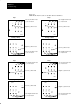
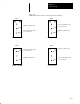
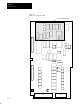
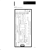
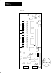
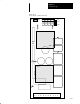
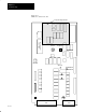
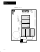
Figure 11.5
IGBT Module Test Procedure for 8510SA-A04 and A06 Drives
IGBT2
IGBT1
IGBT2
IGBT1
IGBT2
IGBT1
IGBT2
IGBT1
Negative (–) Meter Lead
–
+++
Place Positive Meter Lead
(+) on each Screw
Step 3
Step 1
–
+++
Place Negative Meter Lead
(–) on each Screw
Step 4
Step 2
+
–––
Positive (+) Meter Lead
Negative (–) Meter Lead
Place Positive Meter Lead
(+) on each Screw
Positive (+) Meter Lead
Place Negative Meter Lead
(–) on each Screw
+
–––
–––
+
Positive (+) Meter Lead
Place Negative Meter Lead
(–) on each Screw
Positive (+) Meter Lead
Place Negative Meter Lead
(–) on each Screw
–––
+
+++
–
Negative (–) Meter Lead
Place Positive Meter Lead
(+) on each Screw
+++
–
Negative (–) Meter Lead
Place Positive Meter Lead
(+) on each Screw
Reading = Infinity
Reading = 590mV
Reading = Infinity
Reading = 590mV