8510 AC Spindle Drive System User Manual
Important User Information Solid state equipment has operational characteristics differing from those of electromechanical equipment. “Safety Guidelines for the Application, Installation and Maintenance of Solid State Controls” (Publication SGI-1.1 available from your local Allen-Bradley Sales Office or online at http:// www.ab.com/manuals/gi) describes some important differences between solid state equipment and hard-wired electromechanical devices.
Table of Contents 8510 User Manual Introduction Chapter 1 Chapter Objectives . . . . . . . . . . . . . . . . . . . . . . . . . . . . . . . . . . . . . . . . . Manual Objectives . . . . . . . . . . . . . . . . . . . . . . . . . . . . . . . . . . . . . . . . . General Precautions . . . . . . . . . . . . . . . . . . . . . . . . . . . . . . . . . . . . . . . . Drive Overview . . . . . . . . . . . . . . . . . . . . . . . . . . . . . . . . . . . . . . . . . . . 1327A AC Motor Overview . . . . . . . . . . . . .
Table of Contents 8510 User Manual Interface Signal Descriptions Chapter 7 Chapter Objectives . . . . . . . . . . . . . . . . . . . . . . . . . . . . . . . . . . . . . . . . . 7-1 I/O Interface . . . . . . . . . . . . . . . . . . . . . . . . . . . . . . . . . . . . . . . . . . . . . . 7-1 Conventions used in this Manual . . . . . . . . . . . . . . . . . . . . . . . . . . . . . . 7-2 Signal Level Descriptions . . . . . . . . . . . . . . . . . . . . . . . . . . . . . . . . . . .
Chapter 1 Introduction Chapter Objectives Chapter 1 provides information on the general intent of this manual, gives an overall description of the 8510 AC Spindle Drive System, and provides a detailed description of the key features of this drive. This information will help the reader to understand both the basic capabilities and the advanced features of the 8510 drive system and recognize opportunities to use these features to improve machine performance.
Chapter 1 Introduction General Precautions In addition to the precautions listed throughout this manual, the following statements which are general to the system must be read and understood. ! ! ! Drive Overview ATTENTION: Only personnel familiar with the 8510 AC Drive System and associated machinery should plan or implement the installation, start-up and subsequent maintenance of the system. Failure to comply may result in personal injury and/or equipment damage.
Chapter 1 Introduction 1327A AC Motor Overview Drive Design Features The 1327A AC Spindle Motors have been specifically designed to meet the needs of modern machine tools. To cover the variety of application requirements, both a standard series and a dual winding series are available. Some of the key features of these motors include: n Small Size – Advanced electromagnetic and cooling system designs provide extremely compact motors.
Chapter 1 Introduction Servo Mode – configures the drive to be used as a velocity servo in a closed position loop system. Whenever the CNC is operating the spindle drive in a closed position loop, such as during spindle orient or when performing C-axis machining on a turning center, this operating mode should be used.
Chapter 1 Introduction High Resolution Velocity Control Optimum velocity control and smoothness is provided by a 14 bit A/D converter for the command, and a multi-pole resolver with 16 bit resolution for velocity feedback. For C axis operation in Servo Mode, the input can be rescaled to achieve full 14 bit resolution over both the rapid traverse and the feed speed ranges.
Chapter 1 Introduction Control Of Dual Winding Motors A 12:1 constant power range can be obtained by using dual winding motors. AC motors are usually wired internally into either a ∆ or a Y winding configuration. With the dual winding motors, a pair of externally mounted contactors are used to reconfigure the motor windings between ∆ or Y connections while the motor is running.
Chapter 1 Introduction I/O Options The 8510 AC Drive I/O can be configured in several ways as explained below. Standard I/O - Drive Model 8510A-Axx-Ax This is the standard drive I/O and includes the functionality required for normal spindle operations on conventional machine tools. Drive Model 8510A-Axx-Bx In this version, the standard I/O is expanded to include the 16 bit parallel digital input that can be used for either a digital spindle speed command or an external spindle orient position command.
Chapter 1 Introduction System Accessories Various accessories are available for the 8510 to facilitate system installation or to support the drive system. - Mating Connector Kits – All signal interconnections to the 8510 utilize Honda multi-pin connectors. Mating connector kits are available for all the Honda connectors. A mating connector kit is also available for the AMP connector used for feedback from the motor.
Chapter 2 Specifications Chapter Objectives Chapter 2 provides the specifications for the 8510 AC Spindle Drive System. Specifications have been grouped by type of motor. Standard Single Speed 1327AC Motor & 8510 Drive Motor 1327AC - AFM-02 AFM-04 AFM-06 AFL-08 AFL-11 Output Power Rating S1 - Continuous - kW (HP) S2 - 30 Minute - kW (HP)1 S6 - 60% Duty - kW (HP)2 1 Minute Peak - kW (HP) 2.2 (3) 3.73 (5)3 2.6 (3.4) 4.5 (6) 3.7 (5) 5.5 (7.5) 4.3 (5.8) 6.7 (9) 5.5 (7.5) 7.5 (10) 6.6 (8.
Chapter 2 Specifications Standard Single Speed 1327AB Motor & 8510 Drive Motor 1327AB - AFL-15 AFL-19 AFL-22 Output Power Rating S1 - Continuous - kW (HP) S2 - 30 Minute - kW (HP)1 S6 - 60% Duty - kW (HP)2 1 Minute Peak - kW (HP) 15 (20) 18.5 (25) 18.5 (25) 22 (30) 18.5 (25) 22 (30) 22 (30) 26.5 (36) 22 (30) 30 (40) 27 (36) 36 (48) Rated Speed Base RPM Maximum RPM Constant Power/Speed Range 1500 6000 4:1 1500 6000 4:1 1500 6000 4:1 Rated Torque Continuous N-m (lb-ft) 95 (70) 119 (87.
Chapter 2 Specifications Dual Winding Type 1327AD Motor & 8510 Drive Motor 1327AD - ABL-04 ABL-06 ACL-08 ABL-08 Output Power Rating S1 - Continuous - kW (HP) S2 - 30 Minute - kW (HP)1 S6 - 60% Duty - kW (HP)2 1 Minute Peak - kW (HP) 3.7 (5) 5.5 (7.5) 4.5 (6) 6.7 (9) 5.5 (7.5) 7.5 (10) 6.7 (9) 9 (12) 7.5 (10) 11 (15) 9 (12) 13.5 (18) 7.5 (10) 11 (15) 9 (12) 13.
Chapter 2 Specifications Dual Winding Type 1327AD Motor & 8510 Drive (continued) Motor 1327AD - AAK-11 AAK-15 AAK-19 Output Power Rating S1 - Continuous - kW (HP) S2 - 30 Minute - kW (HP)1 S6 - 60% Duty - kW (HP)2 1 Minute Peak - kW (HP) 11 (15) 15 (20) 13.5 (18) 18 (24) 15 (20) 18.5 (25) 18.5 (25) 22 (30) 18.
Chapter 2 Specifications Figure 2.
Chapter 2 Specifications Figure 2.
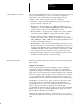
Chapter 2 Specifications Figure 2.1 (continued) Motor Curves 1327AD-ABL-08-E (low speed winding) 8510A-A11-x2 1327AD-ABL-08-E (high speed winding) 8510A-A11-x2 240 12 Peak Torque 9 180 Continuous Power 120 6 3 80 64 30 Minute Power Output Torque (N-m) 30 Minute Power 15 Output Power (kW) Output Power (kW) 12 300 Output Torque (N-m) 15 Peak Torque 9 48 Continuous Power 32 6 60 3 0 0 16 Continuous Torque Continuous Torque 0.2 0.4 0.6 0.8 1.0 1.2 1.4 1.6 1.8 2.0 2.
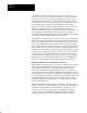
Chapter 2 Specifications Figure 2.1 (continued) Motor Curves 1327AD-AAK-15-x (low speed winding) 8510A-A22-x2 30 300 500 25 250 Output Power (kW) Peak Torque 20 30 Minute Power 400 Continuous Power 15 300 200 10 Continuous Torque 5 0 0.0 0.1 0.2 0.3 0.4 0.5 0.6 0.7 0.8 0.9 1.0 1.1 1.2 1.3 Output Power (kW) 25 600 Output Torque (N-m) 30 20 200 30 Minute Power Continuous Power 15 150 Peak Torque 100 10 100 5 0 0 1.
Chapter 3 Dimensions Chapter Objectives Dimensions for the 8510 system components are detailed on the following pages. Refer to the listing below for help in locating the desired drawing.
Chapter 3 Dimensions Figure 3.1 8510 Drive – A04 10 8 Dia. Mode Scroll + Scroll – Select 433 450 8510 DIGITAL AC SPINDLE DRIVE 27.5 3-18 120 175 8 Dia. 222.
Chapter 3 Dimensions Figure 3.
Chapter 3 Dimensions Figure 3.3 8510 Drive – A06 10 8 Dia. Mode Scroll + Scroll – Select 433 450 8510 DIGITAL AC SPINDLE DRIVE 27.5 3-20 120 175 8 Dia. 222.3 74.
Chapter 3 Dimensions Figure 3.
Chapter 3 Dimensions Figure 3.5 8510 Drive – A11 6 Holes at 7 Dia. Mode Scroll + Scroll – 8510 Select 432 455 DIGITAL AC SPINDLE DRIVE 141.5 283 310 3-22 11.5 13.5 154.
Chapter 3 Dimensions Figure 3.6 8510 Drive – A11 Mounting 16 ∅ 7 Typical, 6 Required 432 400 7.5 Cut Out 141.
Chapter 3 Dimensions Figure 3.7 8510 Drive – A22 6 Holes at 7 Dia. Mode Scroll + Scroll – 8510 Select DIGITAL AC SPINDLE DRIVE 750 727.5 141.5 283 310 3-24 11.5 13.
Chapter 3 Dimensions Figure 3.8 8510 Drive – A22 Mounting 13.5 ∅ 7 Typical, 6 Required 727.5 700 Cut Out 141.5 14 7.
Chapter 3 Dimensions Figure 3.
Chapter 3 Dimensions Figure 3.10 1327AB and 1327AD Series A Foot Mount Motor XN N-W P BH XL XC U S XM ∅AA R AB Shaft Detail AC ES D +0.0 -0.
Chapter 3 Dimensions Figure 3.
Chapter 3 Dimensions Figure 3.12 1327AB Series B, 1327AC Series A and 1327AD Series B Foot Mount Motor P XN XL U XC N-W S XM ∅AA R AB Shaft Detail AC ES Blower D +0.0 -0.
Chapter 3 Dimensions Figure 3.13 High Resolution Magnetic Feedback – Detecting Gear 6 Holes – 5.5 Dia. Equally Spaced 16 B C A D A & B Phase Detecting Gear Catalog Number 8510SA-PG225 8510SA-PG256 8510SA-PG300 8510SA-PG400 8510SA-PG500 8510SA-PG500P 3-30 Z Phase # of Teeth 225 256 300 400 500 500 A 90.8 h6 (0.0/–0.022) 103.2 h6 (0.0/–0.022) 120.8 h6 (0.0/–0.025) 160.8 h6 (0.0/–0.025) 200.8 h6 (0.0/–0.029) 200.8 h6 (0.0/–0.029) B 52 H6 (+0.019/0.0) 65 H6 (+0.019/0.0) 85 H6 (+0.022/0.
Chapter 3 Dimensions Figure 3.14 High Resolution Magnetic Feedback – Sensing Head Minimum Length = 2,000 5.3 Dia., 2 Plcs. 4 ±0.1 50 ±0.1 70 Max. Z Phase Sensor Center A/B Phase Sensor Center 4.9 ±0.5 22.2 Dia. ±0.2 33 Max. 16.5 9 5 Max. 7 ±1 9 0.9 ±0.3 11 +0/–0.02 38 Max.
Chapter 3 Dimensions Figure 3.15 AC Line Fuse Kits – Dimensions are in Inches 8510SA-FA04 8510SA-FA06 1 1 /2 2 17/32 7/32 4 13/16 1 1 /2 3 /4 17/64 Dia. 7/16 C'Bore 4 1/8 2 1/16 8510SA-FA11 2 9/32 5 15/16 19/64 1 1 /2 7/32 Dia. 1/2 C'Bore 6 9/32 3 9/64 1 3 /4 8510SA-FA22 1 1 /2 3/4 C'Bore, 11/32 Dia.
Chapter 3 Dimensions Figure 3.16 Termination Panels 71.0 11 12 1 13 2 14 3 15 16 4 5 17 6 18 7 19 8 DIN #3 Rail A-B Type 199-DR1 or Equivalent (Not Supplied) 20 9 10 86.5 28.0 20 Pin Note: Includes 1.5 m Cable with Connectors on Both Ends 71.0 26 27 1 28 2 29 3 30 4 31 5 32 6 33 7 34 8 35 9 36 10 37 11 39 12 40 14 41 15 42 16 43 17 44 18 45 19 46 20 47 21 48 22 49 23 50 24 25 150.
Chapter 3 Dimensions Figure 3.
Chapter 3 Dimensions Figure 3.18 AC Power Transformer – Dimensions are in millimeters and (inches) B 63.5 (2.5) Typ. 12.7 (0.5) Typ. (if Wall Mounted) M 25.4 (1.0) L C F/2 F P (Knockout) D 25.4 (1.0) Typ. Catalog Number 82.6 (3.25) 50.8 (2.0) F/2 E A N F 14.2 (0.56) Dia. 6 Places. P (Knockout) Weight kg (lb.) A B C D E F L M N 8510T-AA006-BA 8510T-AA009-BA 8510T-AA012-BA 8510T-AA006-EA 8510T-AA009-EA 8510T-AA012-EA 8510T-IA006-BA 438 (17.25) 286 (11.25) 356 (14.00) 375 (14.
Chapter 3 Dimensions End of Chapter 3-36
Chapter 4 Receiving, Unpacking and Inspection Chapter Objectives Chapter 4 provides the information needed to unpack, properly inspect and if necessary, store the 8510 and related equipment. The section entitled Inspection provides a complete explanation of the 8510 catalog numbering system. Receiving It is the responsibility of the user to thoroughly inspect the equipment before accepting the shipment from the freight company. Check the item(s) received against the purchase order.
Chapter 4 Receiving, Unpacking and Inspection 8510 Drive 8510 A – First Position Second Position Bulletin Series Number Letter Description A Series A Design A 04 – Third Position Fourth Position Maximum AC Input Voltage Approx. Continuous Power Output Letter Voltage No. Description A 04 Up to 3.7 kW (5 hp) 200 - 220V AC, ±10%, 50/60 Hz. and 230V AC input, ±10%, 60 Hz 06 11 Up to 5.5 kW (7.
Chapter 4 Receiving, Unpacking and Inspection Transformer 8510T – A A 012 First Position Third Position Fourth Position Continuous kVA Rating Primary Voltage & Frequency Description No.
Chapter 4 Receiving, Unpacking and Inspection Cable Assemblies 8510SA– CA 20D First Position Third Position Fourth Position Connector and Cable Type Cable Length Code Description Letter Description 20D 20 pin connector with cable for digital speed/position input 10 20E 20 pin connector with cable for optical encoder orient feedback Bulletin Number Second Position Cable Assembly – 10 The 20E, 20M and 20R are also available in 30 and 40 meter lengths 20M 20 pin connector with cable for hi
Chapter 4 Receiving, Unpacking and Inspection AC Line Fuse Kits 8510SA – F A04 First Position Third Position Second Position Fuse & Fuse Block Bulletin Number Fuse Ratings Code Description A04 Fuses & fuse blocks for A04 drive A06 Fuses & fuse blocks for A06 drive A11 Fuses & fuse blocks for A11 drive A22 Fuses & fuse blocks for A22 drive Drive Mounting Adapters 8510SA – M P11 First Position Third Position Bulletin Number Second Position Mounting Adapter Adapter Components Code P04 P06 P1
Chapter 4 Receiving, Unpacking and Inspection High Resolution Magnetic Feedback 8510SA – P G225 First Position Third Position Bulletin Number Second Position High Resolution Magnetic Feedback Feedback Elements Code Description G225 G256 G300 G400 G500 G500 PSA Standard class 225 tooth feedback gear Standard class 256 tooth feedback gear Standard class 300 tooth feedback gear Standard class 400 tooth feedback gear Standard class 500 tooth feedback gear Precision class 500 tooth feedback gear Sensi
Chapter 5 Drive Installation Chapter Objectives Drive installation information including environmental conditions and mounting requirements are presented in this chapter. The information presented will serve as a guideline in planning the installation of the drive. Environment Mounting To a flat, rigid, vertical surface. Enclosure Type Sealed enclosure that will prevent drive from being subjected to moisture, oil mist, dust, corrosive vapors, etc.
Chapter 5 Drive Installation ! ATTENTION: The installation of the drive must be planned such that all cutting, drilling, tapping and welding can be accomplished with the drive removed from the enclosure. The drive is of the open type construction and any metal debris must be kept from falling into the drive. Metal debris or other foreign matter that becomes lodged in the drive circuitry frequently results in significant drive damage when power is applied.
Chapter 5 Drive Installation Figure 5.1 Gasket Assembly Enclosure Wall Gasket MO DE SC RO LL (+) SC RO LL (-) Nut SE LE CT DI GI TA LA 85 C SP IN DL 10 ED RI VE Lockwasher Bolt 5. To protect the heat sink from an excessive build up of dirt which will reduce the heat transfer efficiency, a simple sheet metal cover should be placed over the heat sink.
Chapter 5 Drive Installation Figure 5.2 Heat Sink Cover 150 mm (6 in.) Clearance Minimum between Drive and Top of Cover Top of Cover is Solid Air Inlet & Outlet Slots – All 3 Sides 150 mm (6 in.) on Top 75 mm (3 in.) Clearance Minimum between Drive and Bottom of Cover Enclosure Wall Air Inlet & Outlet Slots – All 3 Sides 75 mm (3 in.) on Bottom or Leave Bottom of Cover Open 75 mm (3 in.
Chapter 5 Drive Installation Panel Mounting Panel mounting allows the entire drive to be mounted inside an enclosure without extending the heat sink through the enclosure wall. The drive is mounted inside the enclosure using the panel mounting brackets (Cat. No. 8510SA-Mxxx) that can be supplied as an accessory. Care must be taken to provide the required clearances at the top and bottom of the drive to assure that the airflow across the heat sink is not obstructed.
Chapter 5 Drive Installation Heat Dissipation The drive must always be mounted in a sealed metal enclosure with the heat sinks extending through the enclosure wall, or by using the optional panel mounting brackets (with the heat sinks completely inside the enclosure). In either case the enclosure must be sized to provide adequate surface area to allow the heat generated inside the enclosure (by the drive and other devices) to be dissipated through convection cooling.
Chapter 5 Drive Installation Drive Accessory Mounting Assure that sufficient cabinet space is available to mount the required drive accessories. All wiring is to the bottom of the drive. Provide the necessary clearances for wiring access and wire ways at the bottom of the drive. Fuse Blocks The 8510 does not include the incoming AC line fuses inside the drive for drive component short circuit protection. An optional fuse kit is available that includes the fuse block and fuses.
Chapter 5 Drive Installation End of Chapter 5-50
Chapter 6 Motor Installation Chapter Objectives Chapter 6 provides the information needed to properly install the 1327A AC Motor. Included are environmental conditions that must be met and physical mounting considerations. Mounting Considerations The following items must be considered when mounting the 1327A motor. – The motor can be mounted horizontally or vertically with the shaft down or up.
Chapter 6 Motor Installation Table 6.A 1327A Radial Load Capabilities Motor Catalog Number Maximum Radial Load1 1327AC-AFM-02 133 kg (292 lb.) 1327AC-AFM-04 165 kg (364 lb.) 1327AC-AFM-06 167 kg (368 lb.) 1327AC-AFL-08 313 kg (688 lb.) 1327AC-AFL-11 335 kg (737 lb.) 1327AB-AFL-15 356 kg (784 lb.) 1327AB-AFL-19 373 kg (820 lb.) 1327AB-AFL-22 384 kg (844 lb.) 1327AD-ABL-04 300 kg (660 lb.) 1327AD-ABL-06 310 kg (682 lb.) 1327AD-ABL-08 360 kg (792 lb.) 1327AD-ACL-08 380 kg (836 lb.
Chapter 7 Interface Signal Descriptions Chapter Objectives Chapter 7 provides detailed information on the various inputs and outputs available as part of the 8510 AC Drive System. Included are signal level definitions and detailed function descriptions of each I/O point. I/O Interface The universal I/O interface of the 8510 provides a wide range of inputs and outputs as listed below. Detailed explanations of the inputs and outputs is provided on the following pages.
Chapter 7 Interface Signal Descriptions Analog Outputs – Two analog outputs with 12 bit D/A resolution can be programmed to provide any of the following output signals. • Motor rpm (zero to maximum rpm or – maximum to + maximum rpm) • Spindle rpm (zero to maximum rpm or – maximum to + maximum rpm) • % Load • % Torque • % Power Output • Orient Error (full scale is 2 degrees error) Serial Port – Used for parameter data file upload and download.
Chapter 7 Interface Signal Descriptions Analog Inputs The analog inputs are single ended inputs with the following characteristics: Maximum Input Voltage Range: ±10V DC A/D Converters Two converters selectable via software controlled analog switches. Standard converter for spindle and positioning applications and optional converter for continuous path contouring applications and torque mode operation. A/D Resolution-Standard Converter Effective 14 bits over ±10V DC or 1.22 mV = 1 LSB. Within –0.
Chapter 7 Interface Signal Descriptions I/O Interface Signal Descriptions This section describes the various inputs and outputs available at the standard I/O Interface connector, CN9. See Figure 7.3 for connector location. Digital Inputs Coast to Stop – CN9-1 The Coast to Stop input is wired in series with the coil of an auxiliary relay that directly controls the operation of the main AC input contactor in the drive.
Chapter 7 Interface Signal Descriptions The Enable Torque programmable parameter will determine whether or not holding torque is available from the motor when the Drive Enable input is On. If the parameter is set to “Without Run,” holding torque is available as soon as the Drive Ready output turns On. If the parameter is set to “With Run,” either the Forward Run or Reverse Run inputs must be On before holding torque will be available.
Chapter 7 Interface Signal Descriptions ! ! 7-58 ATTENTION: If an electronic malfunction occurs that prevents the drive from responding to the removal of the Drive Enable input, the motor will continue to operate under power until the user supplied time delayed dropout relay de-energizes and opens the Coast to Stop input.
Chapter 7 Interface Signal Descriptions Figure 7.1 Suggested Regenerative “Emergency” Stop Interface Time Delayed Relay Contacts Coast Coast to Stop CN9-1 User “Emergency Stop” Control Drive Enable Drive Enable CN9-2 +24V DC User Interlocks User Supplied Time Delayed Dropout Relay 0V DC Coast CN9-4, 8, 12 or 17 Drive Reset – CN9-3 When On, any fault conditions that are present will be reset and the drive will begin the initial power-up sequence.
Chapter 7 Interface Signal Descriptions When a digital speed command or a unipolar 0-10V DC analog speed command is used, these two inputs will reverse the direction of motor rotation. When this input is turned Off, the motor will be regeneratively braked to zero speed. Whether or not zero speed holding torque will be available will depend on the setting of the programmable parameter Enable Torque. Figure 7.
Chapter 7 Interface Signal Descriptions When the Torque Enable parameter is set to “Enable,” the Acc Rate #2 parameter is disabled. The Acc Rate #1 parameter is still active in spindle mode. Spindle/Servo Mode Select – CN9-10 This input selects the velocity loop configuration and gains for the spindle or servo operating modes. Refer to page 1-3 for a description of the various control modes. When this input is Off, the spindle mode is active.
Chapter 7 Interface Signal Descriptions If the orient operation is terminated by removing either the Forward or Reverse Run commands, the orient cycle will not automatically resume when the Forward or Reverse Run commands are turned On. The orient command must be applied after the Forward/Reverse Run commands. Gear Ratio Active #1, #2 – CN9-14, 15 Refer to page 1-4 for a description of this function. These two inputs inform the drive of the gear range selected on the machine.
Chapter 7 Interface Signal Descriptions Digital Outputs Current Motor Winding Selected (Low/High) – CN9-18, 19 When this output is Off, the low speed motor winding is connected. When this output is turned On, the high speed winding has been connected. Drive Ready – CN9-20, 21 The Drive Ready output is turned On after the Drive Enable signal has been applied and the drive has successfully completed the power-up sequence (ready for the Forward or Reverse Run commands).
Chapter 7 Interface Signal Descriptions Improper command sequences that would cause a soft fault are; application of the Forward Run, Reverse Run, or Orient commands prior to applying the Drive Enable input. Application of the Motor Winding Select Command - Low when the present motor speed exceeds the maximum allowable motor speed on the low speed winding would also cause a soft fault. Zero Speed Indicator – CN9-26, 27 This output will be turned On when the motor speed drops below 20 rpm.
Chapter 7 Interface Signal Descriptions In servo mode, an analog speed command is required but it can be applied to either analog input. If the SERVO MODE – Analog In # programmable parameter is set to “INPUT #1,” this input must be used for the servo mode analog speed command.
Chapter 7 Interface Signal Descriptions Motor/Spindle Speed These outputs can be programmed to display either motor or spindle speed. The actual motor speed is determined from the resolver feedback and can be output directly, or it can be adjusted for the selected gear range and then output as spindle speed. Full scale calibration is determined by the SPINDLE MODE – Max Cmnd Spd parameter. If spindle speed is being output, the full scale calibration is at Max Cmnd Spd in the highest speed gear range.
Chapter 7 Interface Signal Descriptions Resolver Rotor – CN3-11 & 17 Rotor feedback from the motor resolver.
Chapter 7 Interface Signal Descriptions Thermal Switch – CN3-13 & 20 Thermal switch that is embedded in the motor windings to indicate a motor overtemperature condition. Cable Shields – CN3-1, 2, 3 & 4 The resolver cable must contain twisted shielded pairs with an additional overall shield and all shields must be terminated to these pins. Orient Feedback Signals Connector CN2 provides the connection to the orient feedback sensor when the drive is being used to perform spindle orient.
Chapter 7 Interface Signal Descriptions Magnetic Sensor Channel B Input – CN2-18 & 12 Channel B cosine output from the high resolution magnetic sensor. Magnetic Sensor Channel Z Input – CN2-17 & 11 Channel Z marker pulse output from the high resolution magnetic sensor. Magnetic Sensor Power Supply and Ground – CN2-5 & 3 Control power, +12V DC, to the magnetic sensing head. Dual Winding Contactor Signals Refer to page 1-6 for a complete description of this function.
Chapter 7 Interface Signal Descriptions Digital Command Signals When the drive is supplied with I/O option B or D (Catalog number 8510A-Axx-Bx or 8510A-Axx-Dx), connector CN10 will be present to accept 16 bit digital input signals for spindle speed or orient position commands. Refer to Figure 7.3 for connector location. Refer to Chapter 8 for specific wiring instructions for the connector.
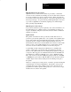
Chapter 7 Interface Signal Descriptions Figure 7.3 8510 Connector Locations Digital Position/Speed Command Standard I/O Orient Feedback CN9 CN10 CN2 Dual Winding Contactor Control Motor Resolver CN1 PE U CN3 V W FE FU FV PE R Motor Fan Power Motor Output S Important: On some 8510A-A06-A1 drives, different designators are used for connectors CN1, CN2, and CN3. Although the connector designator may be different, the I/O function is located in the same physical location as shown.
Chapter 7 Interface Signal Descriptions End of Chapter 7-72
Chapter 8 Wiring Chapter Objectives Chapter 8 provides the information needed to properly wire the 8510 AC Drive System. Included in the chapter are general wiring recommendations and detailed wiring procedures for power and signal wiring. General Wiring Information Since most start-up difficulties are the result of incorrect wiring, every precaution must be taken to assure that the wiring is done as instructed. All items must be read and thoroughly understood before the actual wiring begins.
Chapter 8 Wiring Wire Sizes Unless noted, the wire sizes in this manual are recommended minimums and assume type MTW wire (machine tool wire, 75° C, minimum) per NFPA 79. In all cases, the user is responsible for selecting the appropriate wire type to comply with all applicable national and local codes and to satisfy the needs of the particular application and environmental conditions. Since ambient conditions vary widely, on certain applications, a derating factor has to be taken into account.
Chapter 8 Wiring Grounding All equipment and components of a machine or process system shall have their chassis connected to a common earth ground point. This ground system provides a low impedance path that helps minimize shock hazards to personnel and damage to equipment caused by short circuits, transient overvoltages and accidental connection of energized conductors to the equipment chassis.
Chapter 8 Wiring Figure 8.1 Connector Wiring Short Screw & Nut Cable Clamp Connector Housing Long Screw Washer Clip Connector Honda Connector Wiring and Assembly Refer to the following information and the instruction sheet provided with the connector kit for assembly procedure. 1. Disassemble the connector by removing the 2 short screws and nuts (see Figure 8.1). Since the connector contains a number of small pieces, care should be taken during disassembly. 2. Prepare cable and wire ends.
Chapter 8 Wiring Motor and Drive Power Wiring In accordance with NEC, the power wiring size should be based on the 30 minute overload rating of the applicable motor. The user must determine if national or local codes specify other requirements. All power wiring should be terminated to the bolt or screw terminals on the drive and motor using ring type terminal lugs.
Chapter 8 Wiring Power Transformers The allowable AC input voltage range is 200 to 230V AC, ±10% at 60 Hz and 200 to 220V AC, ±10% at 50 Hz. In larger plants with high capacity power systems, it is not uncommon to encounter exceptionally high AC line voltage that will exceed the +10% specification during part of the day. In these cases the nominal secondary voltage of the transformer should be set for 5-10% less than the maximum allowable nominal input voltage of the drive.
Chapter 8 Wiring Power Wiring AC Input Power To the 8510 Drive AC line input terminals are located at the bottom of the drive as shown in Figure 7.3. Input current requirements and wire size are dependent on the motor kW rating and the AC line voltage. The following table defines the drive AC line input current requirements at a nominal 220V AC line voltage and at the low line voltage limit of 180V AC.
Chapter 8 Wiring Figure 8.2 Recommended AC Input Power Connection Mode Scroll + Scroll – 8510 Select DIGITAL AC SPINDLE DRIVE RST Disconnect and Branch Circuit Overcurrent Protection Supplied by User AC Incoming Power E Optional Isolation Transformer or Autotransformer 8510SA Fuse Kit Drive Component Overcurrent Protection CAT. NO. FREQUENCY POWER RATING PRIMARY VOLTAGE SECONDARY VOLTAGE INSULATION CLASS NO. OF PHASES VENDOR PART NO.
Chapter 8 Wiring Table 8.F Motor Current Requirements Motor Catalog Number Power Rating (Cont. / 30 Minute kW) 1327AC-AFM-02-F 1327AC-AFM-04-x 1327AC-AFM-06-x 1327AC-AFL-08-x 1327AC-AFL-11-x 1327AB-AFL-15-x 1327AB-AFL-19-x 1327AB-AFL-22-x 2.2 / 3.7 3.7 / 5.5 5.5 / 7.5 7.5 / 11 11 / 15 15 / 18.5 18.5 / 22 22 / 30 1327AD-ABL-04-x 1327AD-ABL-06-x 1327AD-ABL-08-E 1327AD-ACL-08-F 1327AD-AAK-11-x 1327AD-AAK-15-x 1327AD-AAK-19-x 1 2 Current Rating (Cont.
Chapter 8 Wiring Figure 8.4 Standard Motor Power Connections Mode Scroll + Scroll – Select 8510 WVU DIGITAL AC SPINDLE DRIVE B2 B1 or e v u FU FE U W V E FV Motor Power and Ground Motor Fan Power and Ground If a 1327AD series dual winding motor is being used, two additional power contactors must be mounted and wired to the drive. Refer to Table 7.A for the specific contactors that are required with each motor. See Figure 8.
Chapter 8 Wiring Figure 8.6 Dual Contactor Wiring Mode Scroll + Scroll – Select 8510 EWVU X Y Z DIGITAL AC SPINDLE DRIVE U VWE X Low Speed Contacts High Speed Contacts Signal Wiring Y Z Auxiliary Contacts I/O Interface Wiring All standard discrete digital control signals and analog inputs and outputs are connected to the drive through the 50 pin CN9 connector. This interface is required for all 8510 systems.
Chapter 8 Wiring Table 8.
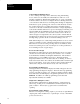
Digital I/O Module (1/2) 8500-E154 VDC1 A12 A13 A14 A15 8510 Drive User's E-Stop Status Relay (K1) CN9-1 CN9-2 CN9-3 9/Series CNC Control I/O E-Stop Terminal Block BT101 Drive Enable Drive Reset CN9-4 CN9-5 Digital Ground CN9-6 Reverse Run CN9-7 CN9-8 Low Torque Limit Select CN9-9 Accel/Decel Rate Select Forward Run Digital Ground CN9-10 Spindle/Servo Mode Select CN9-11 Servo Input Scaling - Low/High User Supplied Power Source CN9-12 Digital Ground CN9-13 Orient Command CN9-14 Gear
Chapter 8 Wiring Resolver Feedback Wiring The motor resolver feedback signals and the motor thermal switch are connected to the drive through the 20 pin CN3 connector. This interface is required for all 8510 systems. Refer to Figure 7.3 for the location of this connector on the drive. The feedback cable can be routed through the same conduit used for motor power leads, but it is essential that a properly shielded cable is used. The cable must have four twisted shielded pairs with an overall shield.
Chapter 8 Wiring A pin extraction tool (AMP # 914677-1) is required to remove a pin from the housing. Both items are available from Allen-Bradley as part of the 8510SA-CTA crimp tool kit. As previously described, three termination options are available for the CN3 connector: l) a mating connector kit, 2) a termination panel, and 3) an interface cable assembly. The following table shows the I/O function assignment for each of these termination options. Table 8.
Chapter 8 Wiring Orient Feedback Wiring In most systems, the spindle orient function can be performed in either the CNC or the spindle drive. If the position control for spindle orient is provided by the drive, the spindle position feedback must be connected to the 8510 through the 20 pin CN2 connector (see Figure 7.3). The 8510 drive can use either a conventional optical encoder or the high resolution magnetic feedback to provide spindle position feedback.
Chapter 8 Wiring Table 8.I Optical Encoder Cable Information Honda Connector Pin Number Signal Description Channel A Output Ground 16 10 Channel B Output Ground 15 9 Channel Z Output Ground 14 8 +12V DC Power Source Ground Cable Shield 5 4 1 Termination Panel Terminal Number Cable Assem. Wire Color and (Pair #) 16 10 Black (1) White (1) 15 9 Red (2) Green (2) 14 8 Brown (3) Blue (3) 5 4 1 Orange (4) Yellow (4) Cable Shield Table 8.
Chapter 8 Wiring Figure 8.
Chapter 8 Wiring Table 8.K Dual Winding Contactor Control Cable Information Signal Description Honda Connector Pin Number Motor Winding Select Command – High Speed 2 Cable Assem.
Chapter 8 Wiring Digital Position/Speed Command Wiring When the 8510 is ordered with the “-Bx” or “-Dx” I/O option, a 16 bit parallel digital command input can be applied through connector CN10. This command can be used for either a digital speed command or orient position command. Refer to Figure 7.3 for the location of this connector on the drive. The interface cable for this function requires 10 twisted pairs with an overall shield.
Chapter 8 Wiring Figure 8.
Chapter 8 Wiring End of Chapter 8-94
Chapter 9 Start-Up Chapter Objectives The steps needed to start-up the 8510 AC Drive System are provided in this chapter. Conventions Used in this Manual To help differentiate input/output names, programmable parameters and programmable values, the following conventions will be used throughout this chapter and the remainder of this manual.
Chapter 9 Start-Up ! ATTENTION: This product contains stored energy devices. To avoid hazard of electrical shock, verify that all voltage on the capacitors has been discharged before attempting to service, repair or remove this unit. A relay connects a resistor across the DC bus to discharge the capacitors. Normally the capacitors will discharge within 15 seconds.
Chapter 9 Start-Up a) Assure that Drive Enable and Coast to Stop are Off. b) Use GEAR RANGES – Select Range to select gear range “1” for programming. If a dual winding motor (1327AD series) is being used, select gear range “1L.” c) Under GEAR RANGES – Default Data, select “YES.” This assures that all parameters are initialized to the default values. d) Under MOTOR SELECT – Catalog Num, scroll down the list of motor catalog numbers and select the number that matches the motor being used in this system.
Chapter 9 Start-Up ! ATTENTION: In the following steps the motor will begin to rotate. It is possible that the motor will rotate at an uncontrolled rate or cause incorrect machine movement. Be prepared to remove drive power by opening the branch circuit disconnect device if this occurs. Incorrect movement may be due to a wiring/programming error or system component malfunction and must be corrected before proceeding with this procedure.
Chapter 9 Start-Up o 12. When a positive analog speed command is applied along with the Forward Run command, the motor should rotate counterclockwise when viewed from the output shaft end. If it does not rotate in this direction, remove the Run and Drive Enable inputs. Use the PARAMETER SET – ELECT CONFIG – Cmnd Phase #1 parameter to reverse the phasing of the input command. Reapply the Drive Enable and Run inputs and check for correct operation. o 13.
Chapter 9 Start-Up ! ATTENTION: If an oscilloscope is used during start-up or troubleshooting, it must be properly grounded. The oscilloscope chassis may be at a potentially fatal voltage if not properly grounded. Always connect the oscilloscope chassis to earth ground. When using an oscilloscope it is recommended that the test probe ground be connected to the test point labeled “GND.” a) Optimum tuning is obtained by observing the small signal step response.
Chapter 9 Start-Up Ideally, if the drive will be operated within a position loop, the final tuning should be performed with the position loop closed by the CNC or other control system. This will allow for the highest overall gains and system stiffness. Independently tuning the velocity loop with step velocity commands leads to a conservative set of tuning parameters.
Chapter 9 Start-Up The orient operation always starts by slowing to the orient speed, locating the marker on the feedback encoder, and then starting decel on the following revolution. Shorter orient times can usually be achieved if the Orient Speed parameter is set relatively high. With a setting of 300 rpm, final decel to the orient position should begin within 200 ms of reaching the orient speed. Adjust the value of Orient Start to give a quick decel without overshoot.
Chapter 10 Display Panel & Fault Diagnostics Chapter Objectives This chapter explains the 8510 display panel and how it is used to show different measurements and perform fault diagnostics. Included is an explanation of the display and descriptions of the various parameters that can be displayed. Menu Format and Conventions The menu system is based on the 16 character by 2 line display used in the 8510. The menu is arranged in a tree format (see Figure 10.1) to allow easy access to any item.
Chapter 10 Display Panel & Fault Diagnostics Display Description The 8510 display which is used for status and diagnostic messages consists of a 16 character, 2 line, LCD (Liquid Crystal) display. The display can be broken into several different sections as shown in Figure 10.2. Refer to the paragraphs that follow for explanations. Figure 10.
Chapter 10 Display Panel & Fault Diagnostics Display Operation The 4 button keypad (see Figure 10.3) is used to access the status and diagnostic systems. Key functions are explained below. Figure 10.3 8510 Keypad and Display Display Keypad Pressing this key will cause the display to change to the previous menu level within the DISPLAY TYPE menu section. If the top item of the menu is shown, the Mode key will have no effect.
Chapter 10 Display Panel & Fault Diagnostics Figure 10.4 Display Type Menu Tree 2L DISPLAY TYPE Line 1 Scroll + Scroll – METER DISPLAY DIAGNOSTICS Line 2 Select Mode Mode Line 1 Line 2 Line 1 2L METER DISPLAY 2L DIAGNOSTICS Scroll + Scroll + Scroll – Motor Speed I/O Inputs Spindle Speed I/O Outputs % Load Current Fault % Torque Hist - #1 ..
Chapter 10 Display Panel & Fault Diagnostics Display Type Menu The DISPLAY TYPE menu is the top level of the menu tree. This will always be the initial top line display when power is first applied to the drive and after the Reset input has been given. METER DISPLAY This is a menu title for all of the parameters that can be displayed in digital meter form on the drive display. The following paragraphs describe the function of each item.
Chapter 10 Display Panel & Fault Diagnostics Orient Error When selected, indicates that the display is currently showing the value of the position error when the drive is in spindle orient mode. This is a bipolar output. Data Format: DEG 00.000 DIAGNOSTICS The information displayed on the diagnostic display can help to isolate a malfunction in the drive. The following paragraphs describe the diagnostic displays available. Refer to Chapter 11 for further troubleshooting information.
Chapter 10 Display Panel & Fault Diagnostics I/O Outputs This parameter indicates the status of all outputs. For ease in identifying each output, successive letters of the alphabet are used to show when they are On. When an output is Off, a dash (–) will be displayed. Refer to Table 10.B for the output associated with each letter. Data Format (line 1): I/O Outputs Data Format (line 2): I/O ABCDEFGHI Table 10.
Chapter 10 Display Panel & Fault Diagnostics End of Chapter 10-110
Chapter 11 Diagnostics/Troubleshooting Chapter Objectives The purpose of this chapter is to assist you in determining the cause of a drive fault or improper drive operation and to define possible corrective actions.
Chapter 11 Troubleshooting Circuit Board Descriptions The functionality associated with each circuit board in the 8510 AC Spindle Drive is described below. Refer to Figure 11.1 for board locations. I/O Board Includes all analog and discrete digital user interface functions along with the integral drive programming system. The EEPROM for user programmed parameter storage is located on this board. Main Control Board Used on 8510A-A11-x2 and 8510A-A22-x2 drives only.
Chapter 11 Troubleshooting Figure 11.
Chapter 11 Troubleshooting Power Distribution and Control The initial power-up sequence is described below. Refer to Figure 11.2 for the associated power distribution and control circuitry. 1. When AC power is applied to the drive, the cooling fans and all internal control logic is immediately energized through AC control power fuse sets F1, F2, and F3. 2. The external Coast to Stop input must be closed to allow any of the following power-up sequence to be executed.
Chapter 11 Troubleshooting Figure 11.
Chapter 11 Troubleshooting Fuse Locations and Types Fuse location and specific fuse information is provided in the paragraphs that follow. AC Control Power Fuses The electrical location of the AC control power fuses is shown in Figure 11.2. Refer to Figures 11.10, 11.13 and 11.14 for fuse locations. Table 11.A provides information on fuse types. Table 11.
Chapter 11 Troubleshooting The gate drive fuses can not be visually checked to determine if they have malfunctioned. The fuse element is too small to allow a reliable visual check. Use an ohmmeter to test these fuses (with power off & out of circuit). ! Fault Diagnostics System ATTENTION: Do not apply power to the drive if any of the IGBT gate drive fuses have opened or been removed.
Chapter 11 Troubleshooting Current Fault Display Text Line 1 Hi Positn Err Display Text Line 2 42 Problem Number Current Fault Hi Speed Cmd 43 Current Fault Current Fault Inv/Mtr Short I/O Comm Err 11 30 Current Fault Current Fault Current Fault Current Fault Current Fault Current Fault Current Fault Current Fault Current Fault Current Fault Current Fault Current Fault Current Fault Main A/D Conv Main Comm Err Main CPU Loss Main CPU Ovfl Main CPU1 Err Main CPU2 Err Main RAM Err Main RAM Init Main
Chapter 11 Troubleshooting ! ! ATTENTION: High voltage that presents an electrical shock hazard is present on the Main Control Board of the 8510A-A11-x2 and 8510A-A22-x2 drives. The upper right half of the board contains the IGBT gate drive circuits, while the upper left quarter contains the power supply. DC bus voltage (approximately 325V DC) is present in both of these areas. These areas contain the voltage warning symbol (see example) and are outlined with a heavy white line.
Chapter 11 Troubleshooting Table 11.D Problems that Occur when AC Power is Applied No. Problem Probable Cause Possible Solutions 1 Display does not illuminate and drive and motor cooling fans do not start. Loss of incoming AC power. Measure AC voltage between terminals R, S, and T on the bottom of the drive to verify that the line to line voltage is 180-253V AC at 60 Hz or 180-242V AC at 50 Hz. Loose power connection in Power Unit.
Chapter 11 Troubleshooting Table 11.D (Continued) Problems that Occur when AC Power is Applied No. Problem Probable Cause Possible Solutions 4 AC Phase Loss displayed - Loss of one phase of incoming AC line detected by drive. An incoming 3 phase line is open. Measure all phase to phase voltages. Check all incoming line connections for tightness. Malfunctioning AC control power fuse. Check fuses FU3R, FU3S, and FU3T. Malfunctioning drive interconnections or hardware. 1.
Chapter 11 Troubleshooting Table 11.E Problems that Occur when Drive Enable is Applied (or during operation) No. Problem Probable Cause Possible Solutions 7 No fault is indicated but the main contactor will not close and the Drive Ready output is not energized. Improper command sequence has been applied. Assure that the Coast to Stop input is energized before any other input command is applied. Assure that Drive Enable is energized before either run command or the orient command. Refer to Figure 7.
Chapter 11 Troubleshooting Table 11.E (Continued) Problems that Occur when Drive Enable applied (or during operation) No. Problem Probable Cause Possible Solutions 9 Convrtr Short displayed - Current sensed by DC link current sensor CT-R was too high. Usually indicates problem with IGBTs in converter bridge. Momentary power outage while motor is regenerating to a stop. Remove power to the drive, and restart. Malfunctioning drive interconnections. 1.
Chapter 11 Troubleshooting Table 11.E (Continued) Problems that Occur when Drive Enable applied (or during operation) No. Problem Probable Cause Possible Solutions 11 Inv/Mtr Short displayed - Current sensed by DC link current sensor CT-S was too high. Usually indicates problem with motor or IGBTs in inverter bridge. See fault condition 10, Motor Short. Malfunctioning drive interconnections. See fault condition 10, Motor Short. 1.
Chapter 11 Troubleshooting Table 11.F Problems that Occur while the Drive is Operating No. Problem Probable Cause Possible Solutions 15 Motor runs in a random or uncontrolled manner or with excessive vibration when either the Forward or Reverse Run command is energized. Resolver phasing is incorrect. Use the programming parameter ELECT CONFIG - Motor Phasing to reverse the relative phasing of the motor to the resolver. Motor phase is open.
Chapter 11 Troubleshooting Table 11.F (Continued) Problems that Occur while the Drive is Operating No. Problem Probable Cause Possible Solutions 18 Bus Undervolt displayed - DC bus voltage less than the minimum allowable level was detected. Incoming 3 phase voltage is out of tolerance. Adjust taps on transformer or add step-up transformer to keep AC line voltage above 180V AC, 50/60 Hz. Incoming AC line impedance is too high.
Chapter 11 Troubleshooting Table 11.F (Continued) Problems that Occur while the Drive is Operating No. 20 Problem Probable Cause Possible Solutions Motor Ovrtemp displayed - The drive detected that the thermal switch in the motor has opened. Motor is overloaded by existing duty cycle. When the motor cools, the thermal switch will close and the fault will clear. Reduce duty cycle loading or increase size of motor/drive system. Motor fan not operating. 1.
Chapter 11 Troubleshooting Table 11.F (Continued) Problems that Occur while the Drive is Operating No. Problem Probable Cause Possible Solutions 22 Spd Error Hi displayed - A motor stall condition or an unexpected motor acceleration or deceleration was detected. If during startup, the motor runs at a constant low speed or reverses direction frequently, the motor versus resolver phasing is incorrect.
Chapter 11 Troubleshooting Table 11.G Problems that Occur during Spindle Orient Operation No. Problem Probable Cause Possible Solutions 24 Motor runs continuously at the Orient Speed parameter setting without faulting and without orienting. Feedback device is incorrectly phased. Use the ORIENT SETUP - FEEDBACK DEFN - Encdr Phasing parameter to reverse the phasing of the orient feedback device. Wrong type of feedback device has been specified.
Chapter 11 Troubleshooting Table 11.G (Continued) Problems that Occur during Spindle Orient Operation No. Problem Probable Cause Possible Solutions 27 Bad PG Count displayed - An incorrect number of spindle position feedback counts was detected between two successive markers pulses as determined by the programmed number of lines on the feedback device. The number of encoder lines has been incorrectly programmed.
Chapter 11 Troubleshooting Table 11.H Other Faults that Indicate Control Hardware Malfunction No. Problem Probable Cause Possible Solutions 29 Main RAM Err displayed- A parity or functional error was detected in RAM on the Main Control Board (CPU Board on A04/A06 drive). RAM is malfunctioning. Replace Main Control Board (CPU Board on A04/A06 drive).
Chapter 11 Troubleshooting Table 11.H (Continued) Other Faults that Indicate Control Hardware Malfunction No. Problem Probable Cause Possible Solutions 35 Main CPU1 Err displayed - The master cpu on the Main Control Board (CPU Board on A04/A06 drive) malfunctioned. Main CPU2 Err displayed - The slave cpu on the Main Control Board (CPU Board on A04/A06 drive) malfunctioned. Main RAM Init displayed- Functional error detected in RAM on Main Control Board (CPU Board on A04/A06 drive).
Chapter 11 Troubleshooting Table 11.I Problems Specifically Related to the I/O Board No. Problem Probable Cause Possible Solutions 44 EEPROM No Data displayed - The I/O Board microprocessor could not find programmed data in the EEPROM. The drive was not programmed. Perform the complete drive setup programming procedure as described in the 8510 Programming Manual (publication 8510-5.2). EEPROM not properly installed or malfunctioning. Verify that the EEPROM is properly installed in the socket.
Chapter 11 Troubleshooting Table 11.J Problems Caused by Programming Errors No. Problem Probable Cause Possible Solutions 52 Bad Comb M & D displayed - The motor and drive catalog numbers that are selected are not compatible with one another. Verify that motor and drive catalog numbers have been programmed for the selected gear range. Verify that the selected motor and drive catalog numbers are a compatible set. A 5.5 kW drive can be used with any motor rated 5.5 kW or smaller.
Chapter 11 Troubleshooting Figure 11.3 Resolver Signals Test Point S1 & Ground Resolver Excitation Signal SIN Wave Approx. 17.6V p-p 0V DC 32µs Test Point S2 & Ground Resolver Excitation Signal SIN Wave 0V DC Approx. 17.6V p-p Test Point R1 & Ground Resolver Feedback Signal 0V DC Approx. 8.
Chapter 11 Troubleshooting Figure 11.4 High Resolution Magnetic Feedback Signals T Test Point A and Ground V DC VP-P where: N = Number of Teeth S = Speed (rpm) 90° Test Point B and Ground V DC VP-P 0.1 - 0.4T VP-P Test Point Z and Ground V DC Installation Face 11-136 Amplitude of A/B: V DC = 2.5V VP-P = 3V Amplitude of Z: V DC = 2.5V VP-P = 3V Sensor CW A/B Phase Gear T depends on the number of gear teeth and gear speed.
Chapter 11 Troubleshooting IGBT Test Procedure The following procedure provides the steps needed to properly test the IGBT modules to determine if replacement is necessary. 1. Remove all power to the drive. Remove the front cover from the drive. 2. Label and remove the three motor wires from the drive terminals U, V and W. 3. Access to the IGBT modules must be gained by removing the following boards: On 8510A-A04 and A06 drives remove the CPU, Gate Drive and I/O Boards.
Chapter 11 Troubleshooting Figure 11.
Chapter 11 Troubleshooting Figure 11.
Chapter 11 Troubleshooting Figure 11.
Chapter 11 Troubleshooting Figure 11.
Chapter 11 Troubleshooting Figure 11.
Chapter 11 Troubleshooting Figure 11.
Chapter 11 Troubleshooting Figure 11.
Chapter 11 Troubleshooting Figure 11.
Chapter 11 Troubleshooting Figure 11.
Chapter 11 Troubleshooting Figure 11.
Appendix A Renewal Parts Introduction The following provides a list of the renewal parts available for the 8510 AC Spindle Drive. Information provided is subject to change. Refer to the 8510 Renewal Parts publication (8510-6.0) for current information. For critical process applications, it is recommended that a complete drive be maintained as a spare.
Appendix A Renewal Parts 8510A-A22-xx Drive Part Number Description 145863 145863 151287 148133 148134 152678 152679 152680 152681 152682 152905 Fuse – FU1R, FU1S Fuse – FU2R, FU2S, FU2T Fuse – FU3R, FU3S, FU3T Gate Drive Fuses 5V DC Power Supply Fuse Main Control Board I/O Board Type -A2 * I/O Board Type -B2 * I/O Board Type -C2 * I/O Board Type -D2 * Keypad/Display Board (included with I/O Board) * To avoid being forced to completely reprogram the drive – remove the EEPROM from the malfunctioning I/O
Publication 8510-5.1 – August, 1993 Supersedes May, 1993 P/N 152824 Copyright 1993 Rockwell International Corporation. All rights reserved.