
Owner manual

3
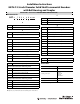
Output Waveforms
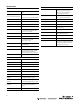
Connector Pins and Signal Availability
Signal Name MS 6-pin MS 7-pin MS 10-pin M12 8-pin
Wire colors,
attached cable
V DC BDD8Red
Common AFF7Black with red band
A output EAA2White
AN output - - H 1 Black with white band
B output DBB4Blue
BN output --I3Black with blue band
Z output CCC6Green
ZN output - - J 5 Black with green band
Zero set input -EE-Yellow
Case FGG-Black
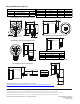
Encoder
connectors
-
Recommended
mating cable
845-CA-A-* 845-CA-B-* 845-CA-C-* 889D-F8FB-* (Attached to encoder)
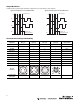
A
B
Z
90°
360°
A
B
Z
90°
360°
Measuring step
B leads A, 180°
marker gated with BN
Signals and marker option - B leads A (CW rotation)
Clockwise rotation when facing encoder shaft
Measuring step
A leads B, 180°
marker gated with A
Clockwise rotation when facing encoder shaft
Signals and marker option - A leads B (CW rotation)
Complementary signals AN, BN, and ZN are supplied only on units with line driver outputs.
A
B
C
F
D
E
A
B
C
F
G
D
E
A
B
C
DE
F
G
H
I
J
4
3
2
1
7
6
5
8