
Owner manual
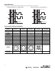

Accessories
f
Code Connector/Cable Exit
AAxial exit
R Radial exit
g
Code Connector/Cable Type
A M12 connector, 8-pin with mating connector
B M12 connector, 8-pin
C MS connector, 6-pin with mating connector
D MS connector, 6-pin
E MS connector, 7-pin with mating connector
F MS connector, 7-pin
G MS connector, 10-pin with mating connector
H MS connector, 10-pin
P 1.5 m (4.9 ft) cable
Q 5 m (16.4 ft) cable
R 10 m (32.8 ft) cable
h
Code Resolution
1…65536 00001...65536 pulses/revolution
Description Part Number
Pre-wired cables 845-CA-*-*
Mating connectors
845-6P
845-7P
845-7P-RT
845-10P
845-10P-RT
Differential encoder buffer board 845-BB*
M12 cable 889D-F8FB-*
* See Sensor Catalog for selection
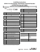
Installation Instructions
847H-F 2.5-inch Diameter Solid Shaft Incremental Encoders
with Bell Housing and Coupler
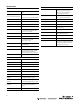
Selection Guide
a
Code Encoder Diameter/Type
H 2.5 in. diameter solid shaft
b
Code Mounting Configuration
F Bell housing and coupler
c
Code Shaft Size
B 1/4 in. diameter bore helical coupler (standard)
E 3/8 in. diameter bore helical coupler (standard)
F 1/4 in. diameter bore bellows coupler (high performance)
G 3/8 in. diameter bore bellows coupler (high performance)
d
Code Power Supply
14.5…5.5V DC
28…30V DC
e
Code Output Configuration
Signal Phasing A-leads-B
clockwise rotation viewed from shaft end, Z gated A
4 4.5…5.5V line driver outputs (TTL)
5 4.5…5.5V open collector outputs
6 8…30V line driver outputs (HTL)
7 8…30V open collector outputs
Signal Phasing B-leads-A
clockwise rotation viewed from shaft end, Z gated BN
A 4.5…5.5V line driver outputs (TTL)
B 4.5…5.5V open collector outputs
C 8…30V line driver outputs (HTL)
D 8…30V open collector outputs
Options 5 and B cannot be ordered with option 2 from table d.
Options 6, 7, C, and D cannot be ordered with option 1 from table d.
847
H
a
-
F
b
c
e
-
01204
B24 AB
dfgh
IMPORTANT: SAVE THESE INSTRUCTIONS FOR FUTURE USE.