
Manual

3
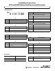
8. Make the electrical connections according to the
Connector Pins and Signal Availability table.
Connector Pins and Signal Availability
Signal Name
Wire color
attached cable
Pin number
M12 8-pin connector
V DC Red 8
Common Black with red band 7
A output White 2
AN output Black with white band 1
B output Blue 4
BN output Black with blue band 3
Z output Green 6
ZN output Black with green band 5
Zero set input Yellow –
Case Black –
Recommended
mating cable
(Attached to encoder) 889D-F8FB-*
M12 pins
on encoder connector
Wiring must be in accordance with the
National Electric Code and applicable local
codes and regulations.
IMPORTANT
4
3
2
1
7
6
5
8
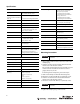
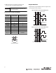
Output Waveforms
Complementary signals AN, BN, and ZN are supplied only
on units with line driver outputs.
A
B
Z
90°
360°
Measuring step
A leads B, 180°
marker gated with A
Signals and marker option - A leads B (CW rotation)
Clockwise rotation when facing encoder shaft
A
B
Z
90°
360°
Measuring step
B leads A, 180°
marker gated with BN
Signals and marker option - B leads A (CW rotation)
Clockwise rotation when facing encoder shaft