
Manual

2
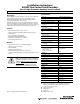
Product Selection
a
b
c
d
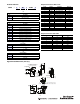
Approximate Dimensions [mm (in.)]
842HR — SJ DZ 115FWY2
abc d
Number of Turns
Code Description
S Single-turn (1 turn)
M Multi-turn (4096 turns)
Mounting Configuration (Note)
Code Description
DZ Square Flange, 3/8 inch solid shaft
DN Square Flange, 3/8 inch solid shaft with flat
A1 Hub Shaft, 15 mm blind hollow shaft
A2 Hub Shaft, 1/2 inch blind hollow shaft
A3 Hub Shaft, 12 mm blind hollow shaft
A4 Hub Shaft, 10 mm blind hollow shaft
A5 Hub Shaft, 3/8 inch blind hollow shaft
A6 Hub Shaft, 8 mm blind hollow shaft
A7 Hub Shaft, 1/4 inch blind hollow shaft
A8 Hub Shaft, 6 mm blind hollow shaft
Power Supply
Code Description
1 5…12V DC
2 7…12V DC
Connector Options
Code Description
2 MS 10-Pin
DM23 17-Pin
31.75 (1.25)
31.74 (1.24)
68.4
(2.7)
52.3
(2.06)
66.5
(2.62)
52.3
(2.06)
Square Flange, Solid Shaft
9.51 (0.3746)
9.51 (0.3744)
29.6
(1.16)
7.6
(0.30)
46.4
(1.8)
19.1
(0.75)
8.71
(0.34)
9.51 (0.3746)
9.51 (0.3744)
29.6
(1.16)
7.6
(0.30)
Solid Shaft with Flat
63.0
(2.48)
15 (0.59) is max. bore size
smaller bores require collets
20°
3.3
(0.13)
1.97
(0.08)
32.5
(1.28)
Hub
Shaft
75.5
(3.0)
93.0
(3.7)
68.4 (2.7)
72.0 (2.83)
66.5 (2.62)
63.4 (2.5)
5.3 (0.21) Dia.
4 places
8-32 UNC-28 0.18 (9.57) min.
3 places 120° apart
on a 47.63 (1.875) B.C.
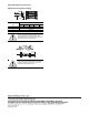
Output Terminations: M23 17-Pin
Pin 12 internally tied to Pin 10.
Output Termination: MS 10-Pin
Pin No. Function Explanation Wire Color
1 SINE Process Data Channel Black
2 REFSINE Process Data Channel White/Black
3 COSINE Process Data Channel Red
4 REFCOSINE Process Data Channel White/Red
5 Data + RS-485 parameter channel Green
6 Data - RS-485 parameter channel White/Green
9DC + Input5V Supply Voltage Gray
10 DC Return Ground Connection White/Gray
11 DC + Input 9V Supply Voltage Orange
13 N.C.
14 N.C.
15 N.C.
16 N.C.
17 N.C.
7 CASE Case Ground Brown
8N.C.
12 DC Return Ground Connection
Pin No. Function Wire Color
A+VSRed
B Common Blue
C Ref SIN Brown
DRef COSBlack
EData +Grey
FData -Green
G SIN White
HCOSPink
I Not used
J Case Case