842E EtherNet/IP™Absolute Encoder User Manual
Important User Information Solid-state equipment has operational characteristics differing from those of electromechanical equipment. Safety Guidelines for the Application, Installation and Maintenance of Solid-State Controls (publication SGI 1.1 available from your local Rockwell Automation sales office or online at http://literature.rockwellautomation.com) describes some important differences between solid-state equipment and hard-wired electromechanical devices.
Table of Contents About this document Who should use this manual . . . . . . . . . . . . . . . . . . . . . . . . . . . . . . . . . . . . . . . Purpose of this manual . . . . . . . . . . . . . . . . . . . . . . . . . . . . . . . . . . . . . . . . . . . . Related documentation . . . . . . . . . . . . . . . . . . . . . . . . . . . . . . . . . . . . . . . . . . . . Common techniques used in this manual . . . . . . . . . . . . . . . . . . . . . . . . . . .
Table of Contents Chapter 5 Configuring the encoder for your EtherNet/IP network Setting the IP Address . . . . . . . . . . . . . . . . . . . . . . . . . . . . . . . . . . . . . . . . . . . . 23 Assigning the last octet in an IP address scheme of 192.168.1.xxx using the network address switches . . . . . . . . . . . . . . . . . . . . . . . . . . . . . . . . . . 23 Assigning the IP Address using BootP/DHCP:. . . . . . . . . . . . . . . . . .
About this document Read this section to familiarize yourself with the rest of the manual. It provides information concerning: • Who should use this manual • The purpose of this manual • Related documentation • Conventions used in this manual Who should use this manual Use this manual if you are responsible for designing, installing, programming, or troubleshooting control systems that use 842E EtherNet/IP™ encoder.
About this document Notes: iv Rockwell Automation Publication 842E-UM001A-EN-P May 2012
Chapter 1 Safety This chapter deals with your own safety and the safety of the equipment operators. Please read this chapter carefully before working with the 842E EtherNet/IP encoder or the machine or system in which the 842E EtherNet/IP encoder is used. Authorized personnel ATTENTION The 842E EtherNet/IP encoder must only be installed, commissioned, and serviced by authorized personnel.
Chapter 1 Safety Considerations for the safety of personnel and systems must be provided by the constructor of the system as per statutory regulations. Due to its design, the 842E EtherNet/IP encoder can only be operated within an EtherNet/IP network. It is necessary to comply with the EtherNet/IP specifications and guidelines for setting up a EtherNet/IP network. In case of any other usage or modifications to the 842E EtherNet/IP, e.g.
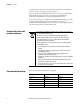
Chapter 2 Encoder overview The 842E family of encoders uses EtherNet/IP technology to provide its data to a programmable controller. These encoders include an embedded EtherNet/IP switch to connect additional EtherNet/IP capable products in series and/or support a device level ring (DLR) topology for ethernet media redundancy. The 842E are ultra-high resolution encoders in single-turn and multi-turn versions. These encoders have 18 bit single-turn resolution.
Chapter 2 Encoder overview Multi-turn units assign a unique digital output for each shaft position across multiple shaft rotations and are capable of extremely high resolutions. Rockwell Automation absolute encoders are available with an enclosure rating of NEMA Type 4 and IP66, as well as a variety of mounting options. Applications include steel mills, overhead cranes, punch presses, transfer lines, oil rigs, wind mills, machine tools, and packaging.
Encoder overview Chapter 2 Configurable parameters The EtherNet/IP technology allows for certain encoder parameters to be configured over the network. • Counting direction • Counts per revolution • Preset value • Velocity output • IP addressing The electronic data sheet file The electronic data sheet (EDS) file contains all the information related to the measuring-system-specific parameters as well as the operating modes of the 842E EtherNet/IP encoders.
Chapter 2 Encoder overview Notes: 6 Rockwell Automation Publication XXXX-X.X.
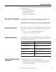
Chapter 3 EtherNet/IP overview Ethernet Industrial Protocol (EtherNet/IP) is a frame-based computer networking technology for local industrial area networks. It follows the seven layers of the Open Systems Interconnection model: OSI Model Layer Function 7. Application Host Layers 6. Presentation 5.
Chapter 3 EtherNet/IP overview TCP/IP and UDP/IP EtherNet/IP uses TCP/IP or UDP/IP for communication. (TCP is transmission control protocol and UDP is user datagram protocol.) Implicit messaging is used for real-time communication between a programmable logic controller (PLC) and the encoder in EtherNet/IP. With implicit messaging a connection is established between exactly two devices within the CIP to transfer, for example, I/O data such as position or velocity from the encoder to the PLC.
EtherNet/IP overview Chapter 3 The ethernet data field consists of several nested protocols: • The IP datagram is transported in the user data of the ethernet data field. • The TCP segment or the UDP datagram are transported in the user data of the IP datagram. • The CIP protocol is transported in the user data of the TCP segment or of the UDP datagram.
Chapter 3 EtherNet/IP overview Specifying the requested packet interval The requested packet interval (RPI) is the update rate specified for a particular piece of data on the network. This value specifies how often to produce the data for that device. For example, if you specify an RPI of 50 ms, it means that every 50 ms the device sends its data to the controller or the controller sends its data to the device. RPIs are only used for devices that exchange data.
EtherNet/IP overview Chapter 3 Linear topology The linear topology uses the embedded switching capability to form a daisychain style network that has a beginning and an end. Linear topology simplifies installation and reduces wiring and installation costs, but a break in the network disconnects all devices downstream from the break. When this topology is used, both ethernet connections on the encoder may be used. For the network connection use Link 1, Link 2, or both.
Chapter 3 EtherNet/IP overview CIP object model EtherNet/IP uses an object model for network communication wherein all functions and data of a device are defined. The important terms are as follows: Class: A class contains related objects of a device, organized in instances. Instance: An instance consists of different attributes that describe the properties of the instance. Different instances of a class have the same services, the same behavior, and the same attributes.
EtherNet/IP overview 23h Position sensor Chapter 3 01h Identity 02h Message router 04h Assembly F4h F5h F6h Network 06h Connection manager The Class Instance Attributes for the position sensor object are provided in the tables below. See Appendix B on page 53 for an example of how to create an explicit message in RSLogix 5000 using the position sensor object tables.
Chapter 3 EtherNet/IP overview Class attributes of the position sensor object Num Required/ (dec) optional Access rule Name Data type Description Default 0x00 02 1 Required Get (implemented) Revision INT Object revision no 2 Implemented Get Max instance INT Max.
EtherNet/IP overview Chapter 3 Attribute ID (dec) Attribute ID (hex) Access rule (1) NV / V (2) Name Data type Description 16 10 Set NV Counts per range DINT 17 11 Set NV Total measuring range DINT 18 12 Set NV Position measuring increment DINT 19 13 Set NV Preset value DINT 21 15 Get V Position status register BYTE 22 16 Set NV Position low limit DINT Min 0x00 00 00 01 Max 0x00 04 00 00 (0x00 04 00 00) Total resolution Min / Max 0x00 00 00 01 / Max. 2^n * Attr.
Chapter 3 EtherNet/IP overview Attribute ID (dec) Attribute ID (hex) Access rule (1) NV / V (2) Name Data type Description 49 31 Get V Warning flag BOOL Indication of set warning 50 32 Get NV Operating time DINT 51 33 Get NV Offset value DINT 100 64 Get V Temperature value INT 101 65 Set NV Temperature value format ENG UNIT 102 66 Set NV Temperature resolution DINT 103 67 Set NV Minimum temperature value setpoint INT Storage of operating time counter [0,1h]
Chapter 4 Installation Mechanical This chapter describes how to install the 842E EtherNet/IP Encoder. Also refer to the installation sheet provided in the box, Publication No. 100000169360. Shaft rotation direction When you view the encoder from the shaft side, the shaft rotation is clockwise (CW) or counterclockwise (CCW), as shown. Mounting with a solid shaft 1. Be sure to select the proper size flexible coupling clamp to mate to the encoder shaft, e.g., 845–FC–*–*.
Chapter 4 Installation 4. Mount the encoder and tighten with three size M4 mounting screws (not supplied). 5. Center the flexible coupling and tighten the set screws. 6. Rotate the machine slowly and verify that the flexible coupling is not deforming beyond specifications. 7. Align machine to its mechanical zero or home position. 8. Remove the screw cover on the back of the encoder and press the preset push button to change the preset value to the current shaft position value.
Installation Chapter 4 9. Remove the screw cover on the back of the encoder and press the preset push button to change the preset value to the current shaft position value. (The factory preset value is zero.) 10. Replace the screw cover. Mechanical specifications Face mount flange 10 x 19 mm Servo flange 6 x 10 mm Blind hollow shaft 8, 19, 12, 15 mm and 1/4, 1/2, 3/8, 5/8 in. Electrical ATTENTION Switch off the power supply.
Chapter 4 Installation Pin assignments Voltage supply Pin Signal Mating cable wire color Function 1 Vs Brown Supply voltage 10…30V DC White Do not use Blue 0V DC (ground) Black Do not use 2 3 GND 4 Ethernet Link Connections – Link 1 and Link 2 Pin Signal Mating Cable Wire Color Function 1 TxD+ White orange Ethernet 2 RxD+ White green Ethernet 3 TxD– Orange Ethernet 4 RxD– Green Ethernet Preset push button ATTENTION IMPORTANT Pressing the preset push button results in
Installation Chapter 4 Electrical specifications Operating voltage 10…30V DC Power consumption 3W Load current 200 mA Resolution per revolution 262,144 Revolutions 4,096 Repeat accuracy ±0.002° Error limit ±0.
Chapter 4 Installation Notes: 22 Rockwell Automation Publication 842E-UM001A-EN-P May 2012
Chapter 5 Configuring the encoder for your EtherNet/IP network Setting the IP Address The 842E encoder is shipped with the network address switches set to 888. You must assign it an IP address using one of the two methods outlined below. You can set the IP address of the 842E encoder using either one of the following methods: 1. Use the network address switches (see figure on page 19) on the encoder to set the last octet of the IP address (192.168.1.xxx) . 2.
Chapter 5 Configuring the encoder for your EtherNet/IP network Assigning the IP Address using BootP/DHCP: Verify that the encoder’s MAC ID is in the relationship list in the BootP Utility or DHCP server before attempting to assign the encoder an IP address using this procedure. 1. Set the three network address switches to 999 and cycle power. 2. Set the three network address switches to 000 and cycle power. 3. The encoder will power up and request an IP address from a BootP/ DHCP server. 4.
Configuring the encoder for your EtherNet/IP network Chapter 5 5. Disable DHCP: click once on the encoder in the relation list to highlight it. Then click Disable BOOTP/DHCP. This instructs the 842E encoder to retain the IP address at the next power cycle. Wait for the status message to show that the command was successfully sent. If the message does not appear, repeat this step. 6. Click File > Save As to save the relationship, if desired. 7. Cycle the power to the 842E encoder.
Chapter 5 Configuring the encoder for your EtherNet/IP network Notes: 26 Rockwell Automation Publication 842E-UM001A-EN-P May 2012
Chapter 6 Configuring the 842 E encoder using RSLogix 5000 This chapter guides you through the steps required to configure your encoder using RSLogix 5000 software. Note that the modules presented in this chapter are configured using RSLogix 5000 software, version 20. Example: setting up the hardware In this example, a CompactLogix™ chassis contains the L35E processor in slot 1 and a built-in EtherNet/IP connection. The encoder is connected to a Stratix 6000 ethernet switch.
Chapter 6 Configuring the 842 E encoder using RSLogix 5000 Configuring the encoder You must configure your encoder upon installation. The encoder will not work until it has been configured with at least the default configuration. RSLogix 5000 configuration software You must use RSLogix 5000, version 18 or later to set configuration for your encoder. The instructions in this chapter use version 20.
Configuring the 842 E encoder using RSLogix 5000 Chapter 6 3. Then open the path AB_ETHIP1, ethernet. The encoder can be seen with its IP address. 4. Install the add-on profile according to the instructions in Appendix A, page 49. IMPORTANT Setting up the add-on profile in RSlogix 5000 Before proceeding, install the add-on profile (see Appendix A, page 49). After you install the encoder add-on profile (see Appendix A, page 49), set up the add-on profile; here is an example of the setup procedure. 1.
Chapter 6 Configuring the 842 E encoder using RSLogix 5000 3. Enter the new controller information. 4. Right-click on the ethernet port of the controller and select New Module.
Configuring the 842 E encoder using RSLogix 5000 Chapter 6 5. Select the desired 842E encoder and click Create. 6. Close the select module type dialog box. 7. Continue to the next sections to complete the add-on profile.
Chapter 6 Configuring the 842 E encoder using RSLogix 5000 General tab 1. Enter a name for the encoder. In this example, the name is Encoder_1. You may have multiple encoders or other modules, so be sure to give each a brief but descriptive name. The name that you assign to the encoder appears in the controller organizer IO tree. The name will also appear in the description of tags. 2. Enter a description of the encoder’s function. 3. Set the ethernet address for the encoder.
Configuring the 842 E encoder using RSLogix 5000 Chapter 6 Ethernet address When the controller is offline, the ethernet address can be set. You have three options: • When a private network is used, click on the Private Network radio button. Enter a value of 1…254 for the last segment (octet) of the address. Be sure not to duplicate the address of an existing device. In the preceding example, the address of the EtherNet/IP encoder is 192.168.1.123.
Chapter 6 Configuring the 842 E encoder using RSLogix 5000 Module definition The user should not have to make changes to the default values. If necessary, follow the steps below to change series, revision, electronic keying, connection, and/or input data. 1. On the General tab, click the Change button. The module definition window opens. 2. Click the arrows at the right of each box to access drop-down menus.
Configuring the 842 E encoder using RSLogix 5000 Chapter 6 Connection tab You should not have to change any settings on the Connection tab. For reference, these are the settings: Requested Packet Interval: Specify the number of milliseconds between requests for information from the controller to the encoder. The encoder may provide data on a shorter interval, but if no data is received the controller asks the encoder for a status update. Minimum setting is 2 ms and the maximum setting is 750 ms.
Chapter 6 Configuring the 842 E encoder using RSLogix 5000 Module Info tab The Module Info tab contains read-only data that is populated when the controller goes on line (a program is downloaded or uploaded from the controller). The left panel, Identification, shows the vendor, product type, product code, revision level, serial number, and product name. The right panel, Status, shows the fault status, internal state (i.e. run mode) and whether the file is owned and Module Identity.
Configuring the 842 E encoder using RSLogix 5000 Chapter 6 Configuration tab The Configuration tab is used to configure the encoder scaling, direction, and set velocity units. Click the Enable Scaling checkbox to change the encoder resolution. Use the Direction drop down box to set the direction of the encoder (check the definition in the old user manual). Use the velocity units to set the velocity units of the encoder.
Chapter 6 Configuring the 842 E encoder using RSLogix 5000 Internet Protocol tab For the purpose of this user manual, the user is expected to use a private address, that is, an address of 192.168.1.xxx. This window is automatically populated with the data.
Configuring the 842 E encoder using RSLogix 5000 Chapter 6 Network tab The Network tab contains read-only data that is populated when the controller goes online. Network Topology: This displays the current network topology as either linear/ star or ring. Network Status: This displays the current network status as normal, ring fault, or unexpected loop detected. The Refresh Communication link appears when communication with the encoder has failed.
Chapter 6 Configuring the 842 E encoder using RSLogix 5000 Configuration Default encoder settings The 842E EtherNet/IP encoder is supplied with the following parameters: • Direction = clockwise • Scaling = none • Steps per revolution = 262,144 • Total resolution = 1,073,741,823 • Preset = 0 • Velocity measuring unit = rpm Preset function The 842E encoder position value is set to zero when the preset function is executed (by the preset push button or EtherNet/IP).
Configuring the 842 E encoder using RSLogix 5000 RSLogix 5000 controller tags Chapter 6 During the encoder installation the encoder tags are automatically loaded as controller tags. This makes the tags available for all programs. In the controller organizer, click on the Controller Tags. The categories of tags appear. The tag name is composed of the encoder name followed by a: • :“C” for configuration • :“I” for input Configuration image table and tags Expand Enc_1:C by clicking “+.
Chapter 6 Configuring the 842 E encoder using RSLogix 5000 Enc_1:I.Fault: Fault status of the encoder. Enc_1:I.Position: Position status of the encoder. If position-status is selected from the input data selection in the encoder definition you will also see alarms and warning status. Enc_1:I.Velocity: Velocity status of the encoder is also included when selecting velocity-status from input data selection in the encoder definition.
Chapter 7 Diagnostics and troubleshooting This chapter describes the diagnostic process to correct and clear fault conditions on the 842E encoder. Cease operation if the cause of the malfunction has not been identified! ATTENTION Stop the machine if you cannot clearly identify the error and/or if you cannot safely rectify the malfunction.
Chapter 7 Diagnostics and troubleshooting LED Net Red flashing Warning, connection time-out Cleared by reset or a new connection Red Error IP address has been assigned to another device already.
Diagnostics and troubleshooting Chapter 7 Ethernet Link LEDs Link 1 and 2 The ethernet link LEDs, Link 1 and Link 2, display the status of the physical connection on the ethernet interface. Link 1 or Link 2 LED Description OFF No link / power off Green solid Ethernet connection established Green flashing Data transmission TxD/RxD Amber solid Interface port locked Amber flashing Data collisions Electromagnetic interference (EMI) can cause incorrect operations or errors in the position value.
Chapter 7 Diagnostics and troubleshooting Warnings Supported warnings (attribute 47+48) Bit Warning Description FALSE (0) TRUE (1) (47) (47) 0 Frequency exceeded Max.
Diagnostics and troubleshooting Chapter 7 Supported alarms (attribute 44+45) Bit Description Description FALSE (0) (44) TRUE (1) (44) 0 Position ERROR Position error Ok ERROR 1 Diagnostic ERROR Diagnostic error Ok ERROR 2…11 Reserved by CIP – – – 12 Vendor: checksum ERROR Checksum error Ok ERROR 13 Vendor: startup ERROR Startup error Ok ERROR 14…15 Vendor specific – – – Errors Sensor error table Fault header [byte] Bit 0 1 Error Description 0 Reserved Reserved 1
Chapter 7 Diagnostics and troubleshooting Fault header [byte] Bit 2 3 Description 16 Position error Single-turn position error (error in the sensor) 0 1 YES A 17 Position error Multi-turn position error (synchronization MA single) 0 1 YES A 18 Position error Multi-turn position error (synchronization quad single) 0 1 YES A 19 Position error Multi-turn position error (internal interface) 0 1 YES A 20 Position error Multi-turn position error (FRAM) Always – 0 NO A 21…23
Appendix A Installing the add-on profile Introduction This appendix shows how to install the add-on profile (AOP) of the encoder with the RSLogix 5000 program. Add-on profiles are files that users add to their Rockwell Automation library. These files contain the pertinent information for configuring a device that will be added to the Rockwell Automation network.
Appendix A Installing the add-on profile 5. At the welcome screen click on Next. 6. Click the radio button to accept the licensing terms, then click Next.
Installing the add-on profile Appendix A 7. Click the Install radio button and then click Next. 8. Click Install to begin the installation.
Appendix A Installing the add-on profile 9. Click Next to install the add-on profile files. 10. Click Finish to complete the installation.
Appendix B RSLogix 5000 sample code This appendix gives examples of using your encoder, including how to use RSLogix 5000 to set and read parameters.
Appendix B RSLogix 5000 sample code Set up the Configuration tab as follows. 1. Set Parameter Scaling to Enable. 2. Set Counts per Revolution to 200. 3. Total Measuring Range will be 51,200. 4. Position the slide/encoder to a known start position. 5. Set the preset value. The preset value will be retained by the encoder through a machine cycle. Setting up your project 54 1. Create a new program file. Select the processor revision and name the project file.
RSLogix 5000 sample code Appendix B 2. In the controller organizer, right-click Ethernet Communication Adapter and select Properties. 3. Configure the controller’s IP address, this example uses 192.168.1.100. Click Apply, then OK.
Appendix B RSLogix 5000 sample code 4. Right-click Ethernet Network and select New Module. 5. Find the encoder add-on profiles under specialty modules. Select the addon profile for either Multi-turn Encoder or Single-turn Encoder, then click Create.
RSLogix 5000 sample code Appendix B 6. The encoder add-on profile configuration will then launch. Name the encoder (In this example it is My_842E). Configure the encoder’s IP address at 192.168.1.101. 7. Click the Configuration tab and set it up as shown per the linear scaling example on page 53. Click Apply, then OK.
Appendix B RSLogix 5000 sample code 8. The encoder can now be seen as configured on the ethernet network in the controller organizer. 9. The project can then be downloaded to the controller.
RSLogix 5000 sample code Using an explicit message configuration to set preset encoder value ATTENTION ATTENTION Appendix B The preset function results in a change of position reading. This can cause unexpected motion which could result in personal injury and damage to the product or equipment. During preset, steps should be taken to ensure the shaft is stationary and will remain so. In this example, a value is sent to the preset attribute in the encoder.
Appendix B RSLogix 5000 sample code 2. Add a new MSG instruction to the program and browse to the Preset_Message data type created in step 1. Then double-click the gray box on the message instruction to configure it. 3. Use the Position Sensor Object to find the values you want to use to send an explicit message. In the Configuration tab select: Message type: CIP generic Service type: Set attribute single Service code: (Automatically populated) Source element: Preset_value (browse to this tag).
RSLogix 5000 sample code Appendix B 4. In the Communication tab, browse to the encoder on the ethernet network, then click OK. 5.
Appendix B RSLogix 5000 sample code 6. Add a normally open contact and a one-shot instruction to initialize the message instruction. 7. After you enter a value into the Preset_Value DINT and toggle the preset contact, the message instruction presets the encoder’s current count value. The position value is changed to the preset value you set. IMPORTANT 62 Always do a Get after a Set to verify the value was changed.
RSLogix 5000 sample code Using an explicit message configuration to read preset encoder value Appendix B 1. Create a new message data type named Read_Preset and a DINT named Preset_Value_Read. 2. Add a new MSG instruction to the program and browse to the Read_Preset data type created in step 1. Then double-click the gray box on the message instruction to configure it.
Appendix B RSLogix 5000 sample code 3. In the Configuration tab select: Message type: CIP generic Service type: Get attribute single Service code: (automatically populated) Source element: Preset_Value_Read (browse to this tag). Instance: 1 Class: 23* Attribute: 13* * hexadecimal values 4. In the Communication tab, browse to the encoder on the ethernet network, then click OK.
RSLogix 5000 sample code Appendix B 5. The Tag tab will be populated for the Read_Preset. 6. Add a normally open contact and a one-shot instruction to initialize the message instruction.
Appendix B RSLogix 5000 sample code 7. Toggle the Get_preset contact, the message instruction returns the preset value form the encoder into Preset_Value_Read DINT.
RSLogix 5000 sample code Using an explicit message configuration to obtain the encoder’s run-time in seconds Appendix B This example is similar to the previous one, “Using an explicit message configuration to read preset encoder value” on page 63. 1. Create a new message data type named Run_Time_Message and a DINT named Run_Time Seconds.
Appendix B RSLogix 5000 sample code 2. Add a new MSG function block to the program, browse to the Run_Time_Message data type created in step 1. Then double-click the grey box to configure the message instruction. 3.
RSLogix 5000 sample code Appendix B 4. In the Communication tab, browse to the encoder on the ethernet network, then click OK. 5. The Tag tab will be populated f or the Run_Time_Message.
Appendix B RSLogix 5000 sample code 6. Add a normally open contact and a one-shot instruction to initialize the message instruction. Toggling the Get_Run_Time contact initiates the message instruction and returns the current run time in seconds into Run_Time Seconds DINT.
Rockwell Automation Support Rockwell Automation provides technical information on the Web to assist you in using its products. At http://www.rockwellautomation.com/support, you can find technical manuals, technical and application notes, sample code and links to software service packs, and a MySupport feature that you can customize to make the best use of these tools. You can also visit our Knowledgebase at http://www.rockwellautomation.