842E-CM Integrated Motion Encoder on EtherNet/IP User Manual
Important User Information Solid-state equipment has operational characteristics differing from those of electromechanical equipment. Safety Guidelines for the Application, Installation and Maintenance of Solid State Controls (publication SGIIN001_-EN-P available from your local Rockwell Automation sales office or online at http:// www.rockwellautomation.com/literature/) describes some important differences between solid-state equipment and hard-wired electromechanical devices.
Table of Contents Important User Information . . . . . . . . . . . . . . . . . . . . . . . . . . . . . . . . . . . . 2 Preface Who Should Use This Manual . . . . . . . . . . . . . . . . . . . . . . . . . . . . . . . . . . . Purpose of This Manual . . . . . . . . . . . . . . . . . . . . . . . . . . . . . . . . . . . . . . . . Common Techniques Used in This Manual . . . . . . . . . . . . . . . . . . . . . . Requirements. . . . . . . . . . . . . . . . . . . . . . . . . . . . . . . . . . . . . . . . . . . . .
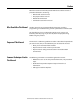
Table of Contents Chapter 5 Example: Setting Up the Hardware. . . . . . . . . . . . . . . . . . . . . . . . . . . . . 29 Configuring the 842E-CM Encoder Checking the Integration in EtherNet/IP via RSLinx Classic. . . 30 Using the Logix Designer Application Adding and Configuring the Add-on Profile in RSlogix 5000 . . . . Adding the Encoder to Your Logix Designer Project. . . . . . . . . Configuring the Encoder . . . . . . . . . . . . . . . . . . . . . . . . . . . . . . . . . . .
Preface Read this section to familiarize yourself with the rest of the manual. It provides information concerning: • Who should use this manual • The purpose of this manual • Related documentation • Conventions used in this manual Who Should Use This Manual Use this manual if you are responsible for designing, installing, programming, or troubleshooting control systems that use the encoder. You should have a basic understanding of electrical circuitry and familiarity with relay logic.
Preface Studio 5000 environment version 21 or later, RSLinx® Classic software version 3.51 or later. Requirements Requirements Components of an Integrated Motion Application 6 System Component Cat. No. Logix Controller Platform 1769-L18ERM 1769-L27ERM 1769-L30ERM 1769-L33ERM 1769-L36ERM CompactLogix™ 5370 controllers with Integrated Motion on the EtherNet/IP network. Linear, device-level ring (DLR), and star topology is supported.
Preface Terminology Term Definition Axis An axis is a logical element of a motion control system that exhibits some form of movement. Axes can be rotary or linear, physical or virtual, controlled or simply observed. Boundary Clock A clock that has multiple PTP ports in a domain and maintains the time scale used in the domain. It may serve as the source of time, for example, a Master clock, and may synchronize to another clock, thus being a Slave clock. CIP Common Industrial Protocol.
Preface Term 8 Definition Quality of Service (QoS) A function that guarantees a bandwidth relationship between individual applications or protocols. Service Data Block The service data block is a lower priority real-time data block associated with a service message from the controller that is transferred by an Integrated Motion on the EtherNet/IP network connection on a periodic basis.
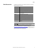
Preface Related Documentation The following documents contain additional information concerning Rockwell Automation products. Resource Description 1756-AP016 CIP Sync brochure 1769-UM021 CompactLogix 5370 Controllers User Manual 1770-4.
Preface Notes: 10 Rockwell Automation Publication 842E-UM002A-EN-P - November 2013
Chapter 1 Safety Precautions This chapter deals with your own safety and the safety of the equipment operators. Please read this chapter carefully before working with the 842E-CM Integrated Motion encoder on EtherNet/IP and/or the machine or system in which the encoder is used. Integrated Motion on Ethernet IP networks requires use of time synchronization. This is explained in the next chapter.
Chapter 1 Safety Precautions Correct Use The 842E-CM Integrated Motion encoder is an instrument manufactured in accordance with recognized industrial regulations, and that meets the quality requirements as per ISO 9001:2008 as well as those of an environment management system as per ISO 14001:2009. An encoder is a device designed to be mounted in a system, and that cannot be used independently of its intended function. For this reason, an encoder is not equipped with immediate safety devices.
Safety Precautions Chapter 1 Environmental Protection Please note the following information on disposal.
Chapter 1 Safety Precautions Notes: 14 Rockwell Automation Publication 842E-UM002A-EN-P - November 2013
Chapter 2 About the Encoder Net XS (Axis) Mod Link 2 Link 1 Screw cover The 842E-CM Integrated Motion encoder on EtherNet/IP provides a feedback-only axis for midrange drive applications on EtherNet/IP networks.
Chapter 2 About the Encoder CIP Sync Overview EtherNet/IP uses CIP Sync and CIP Motion technologies to provide realtime closed-loop motion control with standard Ethernet. This topologyindependent network provides a simplified integration of the entire control solution on one network. CIP Sync provides a mechanism to synchronize clocks between controllers, I/O devices, and other automation products in your architecture with minimal user intervention.
About the Encoder Chapter 2 Star Topology CompactLogix controller programming network CompactLogix 5370 controller Logix Designer application 1 (Front) 2 (Rear) Kinetix 5500 servo drive system 1585J-M8CBJM-x Ethernet (shielded) cable 1585J-M8CBJM-OM3 0.3 m (1.
Chapter 2 About the Encoder Linear Topology The linear topology uses the embedded switching capability to form a daisy-chain style network that has a beginning and an end. Linear topology simplifies installation and reduces wiring and installation costs, but a break in the network disconnects all devices downstream from the break. When this topology is used, both Ethernet connections on the encoder may be used. For the network connection use Link 1, Link 2, or both.
About the Encoder Chapter 2 Device Level Ring Topology A DLR network is a single-fault-tolerant ring network intended for the interconnection of automation devices. DLR topology is advantageous as it can tolerate a a break in the network. If a break is detected, the signals are sent out in both directions. With this topology, use both the Link 1 and Link 2 Ethernet connections on the 842E-CM encoder.
Chapter 2 About the Encoder Notes: 20 Rockwell Automation Publication 842E-UM002A-EN-P - November 2013
Chapter 3 Installation Mechanical This chapter describes how to install the 842E-CM integrated motion encoder on EtherNet/IP. Also refer to the installation sheet provided in the box, publication No. 842E-IN002 (10000481742). Shaft Rotation Direction When you view the encoder from the shaft side, the shaft rotation is clockwise (CW) or counterclockwise (CCW), as shown. Mounting with a Solid Shaft 1. Be sure to select the proper size flexible coupling clamp to mate to the encoder shaft, e.g.
Chapter 3 Installation 2. Use the dimension drawings in the installation instructions to determine the encoder mounting hole locations (see “Related Documentation” on page 9). 3. Slide the flexible coupling onto the shaft, but do not tighten the set screws. 4. Mount the encoder and tighten with three size M4 mounting screws (not supplied). 5. Center the flexible coupling and tighten the set screws. Mounting with a Hollow Shaft IMPORTANT Be sure the mating shaft is chamfered and grease-free. 1.
Installation Electrical Chapter 3 ATTENTION: Switch off the power supply. The machine/system could unintentionally start while you are connecting the devices. Ensure that the entire machine/system is disconnected during the electrical installation. ATTENTION: Commissioning requires a thorough check by authorized personnel! Before you operate a system equipped with the 842E-CM encoder, make sure that the system is first checked and released by authorized personnel.
Chapter 3 Installation Pin Assignments ATTENTION: Wire the voltage supply as shown. Mis-wiring can cause damage to the encoder.
Chapter 4 Configuring the Encoder Configuring the 842E-CM Encoder IP Address This section offers guidance on configuring your Ethernet connection to the 842E-CM encoder. Ethernet Connection Configuration, programming, and diagnosis of the encoder are performed over the standard 10/100 Mbps Ethernet communication port by using the Logix Designer application.
Chapter 4 Configuring the Encoder Assigning the Last Octet in an IP Address Scheme of 192.168.1.xxx Using the Network Address Switches 1. Set the three network address switches to 888. 2. Cycle power to the encoder. 3. Set the three network address switches to a valid address of 001…254. 4. Cycle power to the encoder. 5. The encoder will power up with the IP address set to 192.168.1.xxx, where xxx is the position of the three network address switches.
Configuring the Encoder Chapter 4 Function of Network Address Switch Settings Setting of network address switches Function 001-254 Sets last octet of the IP address to the value indicated (xxx in 192.168.1.xxx) 888 Restores all factory default settings in the encoder and clearing its IP address and enables DHCP. Any other setting Enables last settings (the encoder uses last settings stored in non-volatile memory). ATTENTION: Disable DHCP after the new network address is set (see next step).
Chapter 4 Configuring the Encoder Notes: 28 Rockwell Automation Publication 842E-UM002A-EN-P - November 2013
Chapter 5 Configuring the 842E-CM Encoder Using the Logix Designer Application This chapter guides you through the steps required to configure the encoder using Logix Designer software. Note that the modules presented in this chapter are configured using the Logix Designer application, version 21. Example: Setting Up the Hardware This example features the CompactLogix L36 ERM processor in slot 0 and a built-in EtherNet/IP connection. The encoder is connected to a Stratix 5700™ Ethernet switch.
Chapter 5 Configuring the 842E-CM Encoder Using the Logix Designer Application • Be sure you configured the communication driver (for example, AB_ETH-1 or AB-ETHIP-1) in the RSLinx® software. Checking the Integration in EtherNet/IP via RSLinx Classic Using the tool RSLinx Classic, check again whether the set IP address is accurately detected by the control system.
Configuring the 842E-CM Encoder Using the Logix Designer Application Adding and Configuring the Add-on Profile in RSlogix 5000 Chapter 5 After installing and setting up the encoder, use the encoder add-on profile to add the encoder to the project and configure it. Adding the Encoder to Your Logix Designer Project 1. Apply power to the controller and open the Logix Designer application. 2. From the File menu, choose New. The New Controller dialog opens. 3. Select a controller and name it. 4. Click Next.
Chapter 5 Configuring the 842E-CM Encoder Using the Logix Designer Application 7. Open the Controller Properties. 8. Click the Date/Time tab. 9. Check Enable Time Synchronization. This allows the controller to participate in the Logix Time Synchronization or CIP sync. The controller will also participate in an election in the Logix system for the best GrandMaster clock. 10. Click OK. 11. If needed, in the I/O Configuration, configure an Ethernet module (enable time synchronization and motion).
Configuring the 842E-CM Encoder Using the Logix Designer Application Chapter 5 14. Close the Select Module Type dialog box. The New Module dialog box opens. Configuring the Encoder 1. Configure the new encoder module. a. Type the encoder Name. b. Click an Ethernet Address option. In this example, the Private Network address is selected. c. Enter the address of the encoder. 2. Click the Associated Axes tab. 3. Click New Axis. The New Tag dialog box opens.
Chapter 5 Configuring the 842E-CM Encoder Using the Logix Designer Application 4. Name the new tag. 5. The data type will be AXIS_CIP_DRIVE. 6. Click Create. The new axis (Master_Fdbk) appears under Motion Groups>Ungrouped Axes in the Controller Organizer and is assigned as Axis 1. 7. Click Apply.
Configuring the 842E-CM Encoder Using the Logix Designer Application Chapter 5 Configuring the Motion Group Follow these steps to configure the motion group. 1. Right-click Motion Groups in the Controller Organizer and choose New Motion Group. The New Tag dialog box opens. 2. Type the new motion group Name. 3. Click Create. The new motion group appears under the Motion Groups folder. 4. Right-click the new motion group and choose Properties. The Motion Group Properties dialog box opens. 5.
Chapter 5 Configuring the 842E-CM Encoder Using the Logix Designer Application 6. Click the Attribute tab and edit the default values as appropriate for your application. For this encoder, a coarse update rate from 4…32 ms is supported. If you set the coarse update rate outside that range, you will receive an error message. 7. Click OK. Configuring Axis Properties Follow these steps to configure axis properties. 1. Right-click the axis in the Controller Organizer and choose Properties. 2.
Configuring the 842E-CM Encoder Using the Logix Designer Application Chapter 5 5. Click Apply. 6. Select the Master Feedback category; the Master Feedback specification dialog box opens. 7. Select Type: Hiperface. This is currently the only choice for Type. 8. Set the resolution for the encoder; set the number of turns as appropriate to your encoder. The effective resolution should be displayed. The configuration for multi-turn is shown below. For single turn, Turns should be 1. 9. Click Apply. 10.
Chapter 5 Configuring the 842E-CM Encoder Using the Logix Designer Application 11. Select the Homing category. The default values are Passive Mode and Sequence: Immediate. 12. Enter the desired value for position. This will be the home position. 13. Select Actions. Here you can select the fault exception behavior for your device and the Soft Travel Limits. Shutdown is currently the only available exception behavior.
Configuring the 842E-CM Encoder Using the Logix Designer Application Chapter 5 14. Select Drive Parameters. Check the boxes for desired real-time data. IMPORTANT Firmware revision 1.002 supports the Velocity and Acceleration parameters.
Chapter 5 Configuring the 842E-CM Encoder Using the Logix Designer Application 15. Select the Parameter List category. Enter the necessary changes based on your application requirements. NOTE: Velocity Filter Bandwidth, Acceleration Filter Bandwidth, Velocity Threshold and Velocity Standstill Window cannot be set from the Parameter List. To set these parameters, use the following message instructions. This procedure sends a Logix message to set the following parameters.
Configuring the 842E-CM Encoder Using the Logix Designer Application Chapter 5 b. Set the values in the Message Configuration dialog box as shown. NOTE: The Source Element must be a REAL data type, and its default value is 6000 rps. c. Click the Communication tab and browse to the encoder tag; in this case, “encoder” as shown. The same procedure is required for the following parameters.
Chapter 5 Configuring the 842E-CM Encoder Using the Logix Designer Application Velocity Standstill Window: This value establishes a window around zero speed. When the velocity feedback signal is within this window, the Velocity Standstill status bit is set. If the Velocity Feedback signal falls outside the defined window, the Velocity Standstill status bit is cleared. The source element must be a REAL data type; its default value is 3.0 rps.
Configuring the 842E-CM Encoder Using the Logix Designer Application Chapter 5 Acceleration Filter Bandwidth: (equivalent to Feedback 1 Acceleration Filter Bandwidth in Hz) This value controls the bandwidth of the low pass filter applied to the raw acceleration signal from Feedback.
Chapter 5 Configuring the 842E-CM Encoder Using the Logix Designer Application Sample code is available. Visit the Rockwell Automation Sample Code Library, and search for “CIP motion encoder” or “842E-CM.” To download the sample code with the above information, select Downloads on the following page: http://www.rockwellautomation.
Configuring the 842E-CM Encoder Using the Logix Designer Application Chapter 5 • If you need to change the polarity, select Axis Properties > Polarity. Click the Inverted radio button.
Chapter 5 Configuring the 842E-CM Encoder Using the Logix Designer Application Notes: 46 Rockwell Automation Publication 842E-UM002A-EN-P - November 2013
Chapter 6 Diagnostics and Troubleshooting This chapter describes the diagnostic process to correct and clear fault conditions on the 842E-CM encoder. Refer to MOTION-UM003 for more information. ATTENTION: Cease operation if the cause of the malfunction has not been identified! Stop the machine if you cannot clearly identify the error and/or if you cannot safely eliminate the malfunction.
Chapter 6 Diagnostics and Troubleshooting Net LED Description OFF No power/IP connection Green Connected Green flashing No connection Red Major fault Red flashing Minor fault / Duplicate IP Mod LED Description OFF No power Green Running Green flashing Standby Red Major fault Red flashing Minor fault Green/red flashing Self-test XS (Axis) LED Description OFF No power Green Running Green flashing Standby Red flashing Minor fault or Firmware updating Amber Major fault Am
Diagnostics and Troubleshooting Faults and Alarms Chapter 6 There are four ways to identify and view faults and alarms: • Fault and Alarm log • Quick View pane • Tag Monitor, see the individual fault-related attributes • Status Indicators For more information, see MOTION-UM003 or Appendix C. Troubleshoot Faults The controller may exhibit the following types of motion faults.
Chapter 6 Diagnostics and Troubleshooting Position AxisFaultSubCode Description Hex value Decimal value 1 Over temperature sensor Temperature value of the sensor is out of range 0x1E 30 2 Light control reserve LED current is incorrect 0x1D 0x2C 29 44 3 Frequency exceeded Speed too high (limit exceeded) 0x1F 31 4 Position error Amplitude error Single 0x01 1 5 Position error Amplitude error Multi 0x21 33 6 Position error Vector length single Vector length (Sin² + cos²) 0x1C
Diagnostics and Troubleshooting Chapter 6 Table 3 - Node FLT Fault Codes Exception code on display Exception text Problem Possible solutions NODE FLT 01 – LATE CTRL UPDATE Control Connection Update Fault Several consecutive updates from the controller have been lost.
Chapter 6 Diagnostics and Troubleshooting 842E-CM Exception Behavior For 842E-CM encoders, shutdown is currently the only selectable exception behavior in the Logix Designer application from the Axis Properties dialog box, in the Actions category. Table 5 - Exception Action Definition Exception action Definition Shutdown When the exception occurs, the encoder brings the motor to a stop by using the stopping action defined by the encoder (as in Stop encoder) and the power module is disabled.
Appendix A Flash Update the 842E-CM Firmware Introduction This appendix explains how to flash update new firmware for the 842ECM product. To download the latest firmware for the 842E-CM, copy the following link in your Internet browser, and click on the Go icon: http://www.rockwellautomation.com/rockwellautomation/support/ firmware/overview.page IMPORTANT Check the 842E-CM encoder label before flashing firmware. If the label indicates FW:1.
Appendix A Flash Update the 842E-CM Firmware 2. Start ControlFLASH and select Network or Local network. 3. Click Next. 4. Select the catalog number of the 842E-CM encoder whose firmware you wish to upgrade, then click Next.
Flash Update the 842E-CM Firmware Appendix A 5. Select the controller in the browse window, and click OK. 6. Click Next to continue, and verify the revisions. Click Finish and Yes to initiate the upgrade.
Appendix A Flash Update the 842E-CM Firmware 7. The next screen shows the download progress. 8. If you see an error message instead, click OK to clear the window and power cycle the encoder before trying again. 9. Upon successful completion of the flash update, you see an Update complete status screen. Click OK to complete the update.
Appendix B Installing the Add-on Profile Introduction This appendix shows how to install the add-on profile (AOP) of the encoder with the RSLogix 5000 program. Add-on profiles are files that users add to their Rockwell Automation library. These files contain the pertinent information for configuring a device that will be added to the Rockwell Automation network.
Appendix B Installing the Add-on Profile 5. At the welcome screen, click on Next. 6. Click the radio button to accept the licensing terms, then click Next.
Installing the Add-on Profile Appendix B 7. Click the Install radio button, then click Next. 8. Click Install to begin the installation.
Appendix B Installing the Add-on Profile 9. Click Next to install the add-on profile files. 10. Click Finish to complete the installation.
Appendix C Faults and Alarms Dialog Box The Faults and Alarms dialog box displays the current status of faults and alarms in the controller for an axis. The display is read-only except for the ability to clear logs. Fault and alarm entries are displayed only when you are online with a controller. See also Chapter 6, “Diagnostics and Troubleshooting.” Quick View pane The Quick View pane gives you a quick summary of faults and alarms related to the axis you select in the Controller Organizer.
Appendix C Faults and Alarms Dialog Box Data Monitor 62 The Data Monitor is where you can read and write the values assigned to specific tags, both online and offline.
Rockwell Automation Support Rockwell Automation provides technical information on the Web to assist you in using its products. At http://www.rockwellautomation.com/support, you can find technical manuals, technical and application notes, sample code and links to software service packs, and a MySupport feature that you can customize to make the best use of these tools. You can also visit our Knowledgebase at http:// www.rockwellautomation.