Solid-State Flow Sensors USER MANUAL 839E
Important User Information Because of the variety of uses for the products described in this publication, those responsible for the application and use of this control equipment must satisfy themselves that all necessary steps have been taken to assure that each application and use meets all performance and safety requirements, including any applicable laws, regulations, codes and standards.
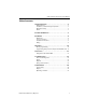
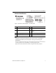
839E Solid-State Flow Sensors User Manual Table of contents Safety instructions . . . . . . . . . . . . . . . . . . . . . . . . . . . . . . . . 2 Designated use. . . . . . . . . . . . . . . . . . . . . . . . . . . . . . . . . . . . . . . . . . . . Installation, commissioning and operation . . . . . . . . . . . . . . . . . Operational safety . . . . . . . . . . . . . . . . . . . . . . . . . . . . . . . . . . . . . . . . . Return . . . . . . . . . . . . . . . . . . . . . . . . . . . . . . . . . . . . . . . .
839E Solid-State Flow Sensors User Manual Safety instructions Designated use The Bulletin 839E is a flow switch for measurement and monitoring of mass flow rates in industrial processes. The device has been safely built with state-of-the-art technology and meets the applicable requirements and EC Directives. It can, however, be a source of danger if used incorrectly or for anything other than the designated use.
839E Solid-State Flow Sensors User Manual Product identification Flow (0.
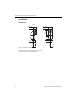
839E Solid-State Flow Sensors User Manual Installation Dimensions M12 x 1 38.7 (1.52) 42.3 (1.66) Dia. 24 (0.95) 38.5 (1.515) Dia. 97.1 (3.82) 42.1 (1.657) 6 (0.24) Dia. 6 (0.24) Dia. L L Figure 2 Dimensions [mm (in.)] Version L with 30 and 100 mm (1.18 and 3.94 in.
839E Solid-State Flow Sensors User Manual Process connection The following table illustrates the versions of 839E. 2 1 L L 43.5 (1.71) dia. 50.5 (1.99) dia. A B C Field of application Measurement and monitoring, mass flow Measuring and monitoring of mass flow rates rates in sanitary processes Process connection Item A Version with thread process connection ANSI ¼-in. NPT (1 = AF14) and ½-in.
39E Solid-State Flow Sensors User Manual Installation instructions 1 Vm L Figure 3 Installing Bulletin 839E (example). Sensor length L is completely immersed in the flow profile. Mounting instructions: • • • • • • • Any orientation The on-site display can be rotated electronically 180° — see “Operation” section. The housing can be rotated up to 310° for optimal readability and ease of wiring. Minimum sensor immersion length: L ≥ 10 mm (0.4 in.) The sensor tip should not touch the pipe wall.
839E Solid-State Flow Sensors User Manual Installation instructions Installation conditions Note! The sensor requires a fully developed flow profile for correct monitoring. For this reason, steadying sections (5x DN) must be provided in the pipe after a pump, pipe bend, internal fittings and cross-sectional changes. ATTENTION Do not turn the device into the process connection thread at the housing. Always install the device at the spanner flats (Figure 4, item 1).
839E Solid-State Flow Sensors User Manual Wiring • The sensor tip should be completely surrounded by medium. • Position the sensor tip in the area of maximum fluid velocity (pipe center). • Minimum sensor immersion length: L1 ±10 mm. Figure 4 Installation conditions Orientation: • For horizontal pipes: lateral installation. Note! Installation from above (see Figure 4) only if the pipe is completely filled with medium during operation. • For vertical pipes: installation in the ascending pipeline.
839E Solid-State Flow Sensors User Manual DC voltage version with M12 connector A2 A1 L+ 2 1 3 4 R1 R2 L+ 2 1 3 4 4…20 mA L- R2 L- Figure 7 DC voltage version with M12 connector Bulletin 839E with M12x1 connector A1: PNP switch outputs R1 and R2 A2: PNP switch output with 4…20 mA analog output Mating cables 2 m (6.5 ft) PVC cable with 4-pin micro (M12x1) connector and ratcheted epoxy-coated zinc coupling nut. Catalog number: 889D-F4AC-2 2 m (6.
839E Solid-State Flow Sensors User Manual Operation On-site programming The Bulletin 839E is programmed via three push buttons. The digital display and the light emitting diodes (LEDs) assist in the navigation through the operating menu. Operating key E LED for status Green = ok Red = error Red/green blinking = warning Digital display 22.
839E Solid-State Flow Sensors User Manual Navigating through the programming menu Figure 9 Navigating through the programming menu A Function group selection B Function selection ➊ Enter the programming menu: - Press and hold the E key for longer than 3 sec. ➋ Once in programming mode (BASE will be displayed), toggle between the Function groups with the + and - keys ➌ To enter the Function group, press the E key ➍ Enter or change parameters with the + or - key.
839E Solid-State Flow Sensors User Manual Navigating the “Learn” function Figure 10 Navigating the “Learn” function using the Calibration (CAL) function group as an example ➊ Select the HIF (Learn High Flow) or LOWF (Learn Low Flow) function with the E key ➋ Select the “RUN” function with the + key, learn function is initialized ➌ Select the “WAIT” function with the + key, press for longer than 2 sec. ➍ Accept (“learn”) the current measured value after approx. 10 sec.
839E Solid-State Flow Sensors User Manual Structure of the operating menu Structure of the operating menu for 1 x analog output (4…20 mA) and 1 x switch output (839E-DCxxxxxx). 1 2 3 80% 0% MAX 3.5 1 Pressing 2 Pressing here navigates to To right display (revert to normal) navigate to 3 To calibrate with setting at 100% press 100% then press . 8 … here navigates to and press .
839E Solid-State Flow Sensors User Manual Structure of the operating menu for two switch outputs (839E-DAxxxxxxx) 1 2 1 1 Pressing here navigates to 2 Pressing here navigates to UNIT and inverts the display . To right display (revert to normal) navigate to and press .
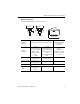
839E Solid-State Flow Sensors User Manual Basic settings Function group Function (display) BASE (basic functions) Description Display assignment: OFF Display of current measured value or of configured switch point (switch 1) Display of current measured value or of configured switch point (switch 1) rotated 180° Display of current medium temperature Display of current medium temperature rotated 180° Factory setting: current measured valued in % Display medium temperature unit °C or °F Factory setting: °C
839E Solid-State Flow Sensors User Manual Function group OUT (Setting for the 1st output) OUT2 (Setting for the 2nd output, optional) Function (display) Description Output switching mode for channel 2: flow or temperature Factory setting: flow Temperature unit selection (°C/°F) NOTE: Function only visible if switching mode (MODE) is set to temperature in the 2nd output. Switch output function: hysteresis function NC contact or NO contact (see diagram) 4…20 mA Enter value 5…100% in increments of 1%.
839E Solid-State Flow Sensors User Manual Function group Function (display) Description OUT and OUT2 (continued) Can be set anywhere between 0…99 sec. in increments of 1 second. Factory setting: 0 sec. SERV (Service functions) Enter the device locking code. Locking, only visible with valid operating code. Resetting of all settings to factory settings. Configuration counter, increments each time the configuration is changed. Display of last error to occur.
839E Solid-State Flow Sensors User Manual Functions of the switch point • Hysteresis function The hysteresis function enables two-point control via a hysteresis. Depending on the mass flow, the hysteresis can be set via the set point SP and the reset point RSP. • N.O. contact or N.C. contact This switch function is freely selectable. Figure 13 Hysteresis function, ➁ N.O. contact, ➂ N.C.
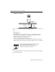
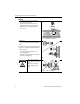
839E Solid-State Flow Sensors User Manual Programming with personal computer and ReadWin 2000 The 839E can also be configured via personal computer and ReadWin software. An additional configuration kit with a conversion cable (Part number 836E-NSR) is required to interface the USB port of the PC to the programming port of the flow switch, as shown below.
839E Solid-State Flow Sensors User Manual Additional operating options In addition to the operating options listed in the “On-site programming” section, the ReadWin configuration software provides an additional function group with further information on the Bulletin 839E: Function group 20 Function (display) Description SERV (service functions) Switching processes 1 Switching processes 2, optional Number of changes in switching status for switch output 1; optionally switch output 2 INFO (device infor
839E Solid-State Flow Sensors User Manual Accessories Configuration Kit with ReadWin The configuration kit (Catalog Number: 836E-NSR) consists of a software CD and a conversion cable which interfaces the USB port of the PC to the 4-pin programming port on the sensor face. USB ReadWin® 2000 software is also available free of charge via download from http://ab.rockwellautomation.com, select Product Directory/Sensors & Switches/ Condition Sensors/Pressure Sensors/Solid-State Pressure Switches/Resources.
839E Solid-State Flow Sensors User Manual Troubleshooting Error and warning codes If an error occurs in the electronics, the color of the status LED changes from green to red and the background illumination of the digital display changes from white to red. A status LED flashing red and green displays an error or warning code, as outlined below: • E-code for errors In the event of an error message, the measured value is unreliable.
839E Solid-State Flow Sensors User Manual Warning Codes Code Explanation W107 Simulation active W202 Flow outside the sensor range W209 Device start-up W210 Configuration modified W212 Sensor signal outside the permitted range W250 Number of switch cycles exceeded W260 Value for High Flow (HIF) and Low Flow (LOWF) faulty W270 Short-circuit and overload at output 1 W280 Short-circuit and overload at output 2 W432 Values for high flow (HIF) or low flow (LOWF) could not be determined with
839E Solid-State Flow Sensors User Manual Technical data Power supply Supply voltage • DC voltage version 18...30 V DC Current consumption • < 100 mA (open-circuit operation) at 24 V DC, max. 150 mA (open-circuit operation); with reverse polarity protection Power supply failure • Behavior in case of overvoltage (> 30V) The device works continuously up to 34V DC without any damage. No damage is caused to the device in case of a short-term overvoltage up to 1 kV (as per EN 61000-4-5).
839E Solid-State Flow Sensors User Manual Operating conditions • Any orientation • Top housing section can be rotated 310° Operating conditions: Environment • Ambient temperature range –40…+85 °C (–40…185 °F) • Storage temperature –40…+85 °C (–40…185 °F) • Climate class 4K4H as per DIN EN 60721-3-4 • Degree of protection IP65 complete housing • Shock resistance 50 g as per DIN IEC 68-2-27 (11 ms) • Vibration resistance 20 g as per DIN IEC 68-2-6 (10-2000Hz) 4 g as per guidelines of German Lloyd GL • Electr
839E Solid-State Flow Sensors User Manual Figure 16 p/T load diagram L = insertion length vW = water fluid velocity = 3 m/s (9.84 ft/s) Flow Switch Conversion Feet per second (ft/s) to gallons per minute (gpm) Conversion ft/s to gpm 1000.0 0.1 0.2 0.4 0.7 0.9 1.1 1.3 1.5 1.8 2.0 2.2 2.4 2.6 2.9 3.1 3.3 0.3 0.6 1.2 1.9 2.5 3.1 3.7 4.3 4.9 5.6 6.2 6.8 7.4 8.0 8.6 9.3 0.6 1.2 2.4 3.6 4.9 6.1 7.3 8.5 9.7 10.9 12.2 13.4 14.6 15.8 17.0 18.2 1.5 3.0 6.0 9.0 12.1 15.1 18.1 21.1 24.1 27.1 30.2 33.2 36.2 39.
839E Solid-State Flow Sensors User Manual Pub #10000004735 Ver 03, May 2012 27
839E Solid-State Flow Sensors User Manual 28 Pub #10000004735 Ver 03, May 2012
839E Solid-State Flow Sensors User Manual Pub #10000004735 Ver 03, May 2012 29
Publication 10000004735 Ver 03 — May 2012 © 2012 Rockwell Automation. Printed in the U.S.A.