Solid-State Pressure Sensors USER MANUAL 836E
Important User Information Solid-state equipment has operational characteristics differing from those of electromechanical equipment. Safety Guidelines for the Application, Installation and Maintenance of Solid-State Controls (Publication SGI-1.1 available from your local Rockwell Automation sales office or on-line at http://www.ab.com/manuals/gi) describes some important differences between solid-state equipment and hard-wired electromechanical devices.
Table of Contents Table of Contents 1 Safety Instructions . . . . . . . . . . . . . . . . . . . . . . . . . . . . . . . 4 1.1 1.2 1.3 1.4 Designated Use . . . . . . . . . . . . . . . . . . . . . . . . . . . . . . . . . . . . . . . . . . . . . . Installation, Commissioning, and Operation . . . . . . . . . . . . . . . . . . . . . . . . Operational Safety . . . . . . . . . . . . . . . . . . . . . . . . . . . . . . . . . . . . . . . . . . . . Return . . . . . . . . . . . . . . . . . . . . . . . . . . . . .
Safety Instructions 1 Safety Instructions 1. 1 Designated Use The Bulletin 836E is a pressure switch for measuring and monitoring absolute and gauge pressures. The device has been safely built with state-of-the-art technology and meets the applicable requirements and EC Directives. It can, however, be a source of danger if used incorrectly or for anything other than the designated use. 1.
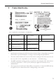
Product Identification 2 Product Identification PNP / 4…20mA 836E-DC1CC1D4 Fig. 1: Explanation of the nameplate - see table below 1 Catalog number 6 Max. working pressure 11 Wiring diagram 2 Series letter 7 Wetted part materials 12 Approvals 3 Serial number 8 Output 4 Enclosure rating / Ingress protection 9 Current consumption 5 Operating pressure 10 Operating voltage Notes: • Specifications and ratings may differ from those shown in Figure 1, depending on particular model.
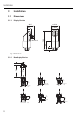
Installation 3 Installation 3. 1 Dimensions 3.1.1 Display Version ø 42.3 38.7 ø 38.5 105 24 11 52 M12x1.0 Fig. 2: Dimensions 3.1.2 Nondisplay Version 15 (0.59) 69 (2.72) 27.5 (1.08) 4 (0.16) Dia. hole 1/2 in. NPT 14 (0.55) Flush Mount DIN 6 1/4 in. NPT 12 (0.47) deep 1/2 in. NPT 1/4 in. NPT 5 (0.2) 20 (0.79) 3 (0.12) G 1/4 3852 3.5 (0.14) Dia. hole 12 (0.47) 17 (0.67) G 1/2 26 (1.02) Dia. 20 (0.79) 25 (0.98) 25 (0.98) G 1/2 6 (0.24) 3 (0.
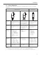
Installation 3. 2 Process Connection The following table outlines the characteristics of the Bulletin 836E, its process, and sanitary connections.
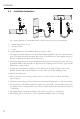
Installation 3. 3 Installation Instructions ➀ ➁ ➀ ➀ ➁ ➁ Gas Steam ➂ ➂ Liquid Fig. 3: Typical applications of the Bulletin 836E to measure pressure in gases, steam and liquids. ➀ Bulletin 836E pressure switch ➁ Shut-off assembly ➂ U-pipe For typical applications of the Bulletin 836E, see Figure 3 above: • The image on the left illustrates how the 836E should be applied for pressure measurement in gases.
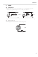
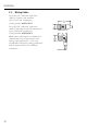
Installation 3. 4 Wiring 3.4.1 Display Version The 836E is a DC voltage switch with two PNP outputs or a single PNP output with a 4…20 mA analog output. Both options feature an M12 (micro) connector. + 2 1 3 4 Load 1 Load 2 12…30V dc + 2 1 3 4 Load 2 12-30V dc 4... 20 mA – – Fig. 4: Bulletin 836E with two PNP switch outputs or one PNP output with 4…20 mA analog output. 3.4.2 Nondisplay Version The nondisplay version is offered with 4…20 mA analog output. + 12 … 30V DC 4...
Installation 3. 5 Mating Cables 2m (6.5ft) PVC Cable with 4-pin micro (M12x1) connector and ratcheted epoxy-coated zinc coupling nut. Catalog number: 889D-F4AC-2 2m (6.5ft) PVC Cable with 4-pin micro (M12x1) right-angle connector and ratcheted epoxy-coated zinc coupling nut.
Operation 4 Operation 4. 1 On-Site Programming The Bulletin 836E is programmed via three push buttons. The digital display and the light emitting diodes (LEDs) assist in the navigation through the operating menu. Operating key E LED for status Green = ok Red = error Red/green blinking = warning Digital display 22.07 bar Yellow LEDs for switching states LED on = switch closed LED off = switch open Communications jack for personal computer Fig.
Operation 4.1.1 Navigating Through the Programming Menu Refer to the menu structure in Figure 4.1.2 on the following page. The section labeled A refers to Function groups The section labeled B refers to the individual Functions within each Function group The section labeled C identifies the possible values for each function ➀ To enter the operating menu: • Press and hold the E key for longer than 3 sec.
Operation 4.1.2 Structure of the Programming Menu The chart below illustrates the structure of the programming menu. • Fig.
Operation 4.1.3 Basic Settings Base 14 Basic settings Unit of measure Select technical unit: bar psi kPa % Configure zero point Position adjustment: within ±20% of the upper range limit Accept zero point Current value as zero point (max. ±20% of the upper range limit) Display PV: measured value display PVRO: measured value display rotated 180° SP: set set point display SPRO: set point display rotated 180° OFF: display off OFFR: display off rotated 180° Damping: display value, output signal 0...
Operation 4.1.4 Output Setting • Hysteresis mode The hysteresis mode allows for two-point control. Depending on the pressure p, the hysteresis can be set via the set point SP and the reset point RSP. • Window mode The window mode enables process pressure range monitoring. • Analog output mode The analog output mode returns a 4…20 mA signal proportional to the measured value. The upper and lower range values can be set by the user.
Operation OUT/OUT2 Output/Output 2 Switching mode HYNO: Hysteresis/NO contact HYNC: Hysteresis/NC contact WINO: Window/NO contact WINC: Window/NC contact 4...20 mA: Analog mode (analog output versions only) Set point value Set point 0.5...100% URL in increments of 0.1% (min. 0.001 bar) Reset point value Reset point 0...99.5% URL in increments of 0.1% (min. 0.001 bar) Set point delay Delay time 0...99 sec. in increments of 0.1 sec. Reset point delay Delay time 0...99 sec. in increments of 0.1 sec.
Operation 4 - 20 Analog output Value for 4 mA (LRV) Enter lower range value in increments of 0.1% Value for 20 mA (URV) Enter upper range value in increments of 0.1% Pressure applied for 4 mA (LRV) Use measured pressure as lower range value Pressure applied for 20 mA (URV) Use measured pressure as upper range value Error current Current value in event of error: MIN = ≤ 3.6 mA MAX = ≥ 21.
Operation 4.1.5 Service Function Setting • Locking Code A locking code already assigned can only be changed by first entering the old code for enabling the device. SERV 18 Service functions Security locking/password protection Enable password protection Password/code entry Select code 1...
Operation 4. 2 Programming with Personal Computer and ReadWin 2000 The 836E can also be configured via personal computer and ReadWin software. An additional configuration kit with a cable (Cat. No. 836E-NSR) is required to interface the USB port of the PC to the programming port of the pressure sensor, as shown below. 1 2 USB 3 Fig. 8: Programming with PC ➀ Personal computer with ReadWin configuration software ➁ Configuration kit (836E-NSR) ➂ Bulletin 836E with programming port Fig.
Operation 4.2.
Accessories 5 Accessories 5. 1 Process Connection • 836E The process connection is an adapter and the sensor module has an adapter thread. As a result, the process connection can be easily changed at a later stage. 1 2 3 M24x1.5 Fig.
Accessories 5.1.1 Adapter Change The adapter can be changed on 836E. Process Adapter Sanitary Adapter 3 3 Fig. 11: Changing the adapter ➀ Sensor module with adapter thread ➁ Standard O-ring ➂ Adapter Please note the following when changing the adapter: 22 • Use a new O-ring. Diameter 15.54 x 2.62 mm (0.61 x 0.10 in.) with either EPDM 70 Shore FDA or FKM 70 Shore FDA material • The sensor can be mounted with a 27 mm open-ended wrench.
Accessories 5.1.2 Adapter Versions Catalog numbers for thread adapter versions (see diagram for dimensions): Sanitary Adapters 1 to 1-1/2-in. clamp: 836E-NH7B 2-in. clamp: 836E-NH7C 836E-NH7B (1 to 1-1/2-in. clamp) SW28 836E-NP76 8.5 836E-NP73 17 Process Adapters G1/4 female: 836E-NP73 G1/4 male: 836E-NP76 7/16 - 20UNF female: 836E-NP72 7/16 - 20UNF male: 836E-NP75 1/4-in. NPT female: 836E-NP71 1/4-in. NPT male: 836E-NP74 Ø50.5 12 15.5 34 34 Ø43.5 G1/4 Ø23 836E-NH7C (2-in.
Accessories 5. 2 Welding Bosses 5.2.1 Welding Boss with Sealing Taper Welding boss for flush mounting process connection with metallic sealing taper. 27.5 Material: AISI 316L 50 Fig. 12: 836E-NWT 5.2.2 Welding Boss with Sealing Surface Welding boss for flush mounting process connection with sealing surface. Material: AISI 316L Seal (enclosed): silicone O-ring % .73 n Fig.
Accessories 5. 3 Configuration Kit with ReadWin The configuration kit (Cat. No. 836E-NSR) consists of a software CD and a conversion cable which interfaces the USB port of the PC to the 4-pin programming port on the sensor face. USB ReadWin® 2000 software is also available free of charge via download from www.ab.
Troubleshooting 6 Troubleshooting 6. 1 Error and Warning Codes If an error occurs in the electronics, the color of the status LED changes from green to red and the display shows an error or warning code, as outlined below: • E-code for errors In the event of an error message, the measured value is unreliable. • W-code for warnings In the event of a warning, the measured value is still reliable.
Troubleshooting Warning Codes Code Explanation W107 Simulation active W202 Pressure outside the sensor range W209 Device start-up W210 Configuration modified W212 Sensor signal outside the permitted range W250 Number of switch cycles exceeded W270 Short-circuit at output 1 W280 Short-circuit at output 2 6. 2 Spare Parts O-ring for adapter change • O-ring 15.54 x 2.62 mm (0.61 x 0.10 in.), EPDM 70 Shore FDA, Catalog no. 836E-NV1 • O-ring 15.54 x 2.62 mm (0.61 x 0.10 in.
Technical Data 7 Technical Data 7. 1 Display Version 7.1.1 Power Supply Supply voltage • DC voltage version 12...30V DC Current consumption • Without load < 60 mA, with reverse polarity protection Power supply failure • Behavior in case of over voltage The device works continuously without any damage up to 34V DC. If the supply voltage is exceeded, the properties specified are no longer guaranteed. • 7.1.
Technical Data 7.1.3 Operating Conditions Any orientation Any position-dependent zero shift can be corrected Position adjustment (offset): ±20% of the upper range limit Operating conditions: Environment • Ambient temperature range –40...+85 °C (briefly up to +100 °C [212 °F]), (–40...+185 °F) • Storage temperature –40...+85 °C (–40...+185 °F) Operating conditions: Process • Medium temperature ranges −40...+100 °C (–40...
Technical Data 7. 3 Pressure Conversion Chart Fig.
Back Cover
Part No. 75054-003 Ver 04 © 2008 Rockwell Automation. Printed in the U.S.A.