Bulletin 825-P Modular Protection System Quick Start Guide
Quick Start Guide — Allen-Bradley Bulletin 825-P Modular Protection System IMPORTANT Important User Information This guide Does Not replace the User Manual, publication 825-UM004_-EN-P, and is intended for qualified service personnel responsible for setting up and servicing these devices. You must have previous experience with and a basic understanding of electrical terminology, configuration procedures, required equipment, and safety precautions.
Quick Start Guide — Allen-Bradley Bulletin 825-P Modular Protection System Attention statements help you to: • • • Identify a hazard Avoid a hazard Recognize the consequences IMPORTANT Identifies information that is critical for successful application and understanding of the product. Trademark List DeviceNet and the DeviceNet logo are trademarks of the Open Device Vendors Association (ODVA). Microsoft Windows is a registered trademark of the Microsoft Corporation.
Quick Start Guide — Allen-Bradley Bulletin 825-P Modular Protection System Low Voltage Directive This product is tested to meet Council Directive 73/23/EEC Low Voltage as amended by 93/68/EEC by applying the safety requirements of EN 60947-4-1 and EN 60947-5-1. For specific information required by EN 60947-4-1 and EN 60947-51, see the appropriate sections in this publication. To obtain a copy of the 825-P’s Declaration of Conformity (DoC), contact your local Allen-Bradley distributor or go to http://www.
Quick Start Guide — Allen-Bradley Bulletin 825-P Modular Protection System General Precautions ATTENTION ! ATTENTION ! ATTENTION ! ATTENTION ! Hardware Installation Have only qualified personnel service this equipment. If you are not qualified to service this equipment, you can injure yourself or others, or cause equipment damage. Equipment components are sensitive to electrostatic discharge (ESD). Undetectable permanent damage can result if you do not use proper ESD procedures.
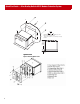
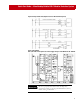
Quick Start Guide — Allen-Bradley Bulletin 825-P Modular Protection System ➀ ➁ 18 (7. 6.0 32 ) ➂ Legend mm (in) 138.0 (5.43) 19 (7. 2.0 56 ) 0 4. ) 14 .67 (5 ➀ Mounting Panel–maximum thickness 6.5 mm ➁ #8 x 1/2 inch mounting screw; Torque specification = 0.9...1.3 N.m (8...12 Lb-in) ➂ Gasket 147.4 (5.80) 20.8 (0.
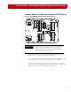
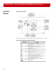
Quick Start Guide — Allen-Bradley Bulletin 825-P Modular Protection System Converter Modules and Optional Core Balance CT, RTD Scanner Figure 3 Converter Module, CBCT, and RTD Scanner Connections IMPORTANT Settings associated with options or accessories (converter module, voltage input card, expansion I/O card, RTD scanner) require their installation or connection prior to being made available for configuration. 1.
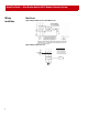
Quick Start Guide — Allen-Bradley Bulletin 825-P Modular Protection System Wiring Installation Main Circuit Figure 4 Relay with Phase CTs and CoreBalance CT Figure 5 Relay without Phase CTs L1 L2 L3 1 3 5 A1 K1 A2 825-MCM 2 4 M 3~ 8 6 Converter Module Cat. No. 825-MCM2 Cat. No. 825-MCM20 Cat. No. 825-MCM180 Cat. No. 825-MCM630 Cat. No.
Quick Start Guide — Allen-Bradley Bulletin 825-P Modular Protection System Figure 6 Voltage Connections (Optional Card Cat. No. 825-PVS required) Figure 7 Input/Output Slots C, D and E are for option cards. Rated supply voltage is 110...240V AC or 110...250V DC IMPORTANT Be sure to properly label and connect the Trip relay terminals according to the programmed behavior; factory default setting is “Fail-Safe”.
Quick Start Guide — Allen-Bradley Bulletin 825-P Modular Protection System Front Panel Operation Figure 8 Relay Front Panel The following table provides a description for each programming key’s function.
Quick Start Guide — Allen-Bradley Bulletin 825-P Modular Protection System Saving Settings It is important to note that programmed values become operational only after they have been saved to memory. The programming system will prompt to save settings when the user navigates higher up in the programming menu by pressing the ESCape key. The front panel display is as follows: Save Changes? Yes No To save changes, place the cursor at “Yes” and press the Enter System Configuration key.
Quick Start Guide — Allen-Bradley Bulletin 825-P Modular Protection System IMPORTANT If the system check finds interdependency setting errors, the front panel display: Settings Mismatch An example of mismatched settings is the correlation between the Motor FLA and Phase CT Ratio settings.
Quick Start Guide — Allen-Bradley Bulletin 825-P Modular Protection System Port 4 Settings The Port 4 settings configure slot C for communications. Factory default settings are for DeviceNet communications. Use the following path with the front panel programming keys to access the Port 4 settings: MAIN > Set/Show > Port > Port 4 The following table provides direction for the proper settings associated with each communication option.
Quick Start Guide — Allen-Bradley Bulletin 825-P Modular Protection System Programming General Parameters Use the following path with the front panel programming keys to access the general parameter settings: MAIN > Set/Show > Port MAIN > Set/Show > Date/Time MAIN > Set/Show > Password Port: In addition to configuring Slot C (Port 4) for communications as described in Step 4, settings are available for configuring the Port F (front panel) RS 232 communications.
Quick Start Guide — Allen-Bradley Bulletin 825-P Modular Protection System Programming Operational Parameters Use the following path with the front panel programming keys to access the operational parameter settings: MAIN > Set/Show > Relay > [Group] Table D: Operational Parameters Group Main Settings Description Basic system settings related to three-phase power source (e.g. line voltage rating and frequency), motor rated current, and transformer (current and voltage) data.
Quick Start Guide — Allen-Bradley Bulletin 825-P Modular Protection System Programming Protection Parameters Use the following path with the front panel programming keys to access the protection parameter settings: MAIN > Set/Show > Relay > [Group] Table E: Protection Parameters Group Overload Settings Short Ckt Settings GF-CB Settings GF-Res Settings Jam Settings Undercurrent Settings Current Imb Settings Prot.
Quick Start Guide — Allen-Bradley Bulletin 825-P Modular Protection System ATTENTION Protection elements have no effect until they are assigned to the Trip relay or an auxiliary relay. ! To assign functions to the output relays and inputs, use the following path: MAIN > Set/Show > IO Assign TIP The relay outputs will function as a N.C. contacts when the relay behavior setting is Fail-Safe (Y), and will function as a N.O. contacts when the relay behavior setting is Non-FailSafe (N).
Quick Start Guide — Allen-Bradley Bulletin 825-P Modular Protection System Trip Relay Assign The 825-P allows mapping of only protection trip elements to the Trip output relay. Settings are presented as bit-enumerated strings. The second line of the display identifies a given bit’s associated function. To assign a function to the Trip relay, simply program a value “1” in the bit location for each element you desire to assign using the TRIP A through TRIP D settings.
Quick Start Guide — Allen-Bradley Bulletin 825-P Modular Protection System AUX# Assign The 825-P allows mapping of protection (trip and warning) and general-purpose control elements to the auxiliary outputs. Assign functions to the auxiliary relays in the same manner as performed with the Trip relay settings.
Quick Start Guide — Allen-Bradley Bulletin 825-P Modular Protection System IN# Assign The 825-P provides the ability to assign a control function to each discreet input. Table H shows the available control functions and the method of assigning them. Table H: Input Function Assignment IN# Emergency Start Disable Settings Trip Reset Timer 1 Timer 2 Speed Switch Block Protection Speed 2 Breaker/Contactor Auxiliary Remote Trip 0 1 2 3 4 5 6 7 0 1 TIP The 825-P allows only one selection per input assignment.
Quick Start Guide — Allen-Bradley Bulletin 825-P Modular Protection System Appendix A: Menu Structure IMPORTANT Figure 12 Menu Structure Visibility of some settings depends upon the system hardware configuration. For example, RTD settings are viewable only when the optional RTD Scanner is connected and communicating with the 825-P relay. Power Up or Steps back one level Main Menu or Instantaneous Thermal Meter See Fig. 13 for more details. Display Events Events Reset Events See Fig.
Quick Start Guide — Allen-Bradley Bulletin 825-P Modular Protection System Figure 13 Main Menu > Meter Meter Steps back one level Instantaneous L1 Curent L1 Angle L2 Current L2 Angle L3 Current L3 Angle GF Curr (Core B) GF-CB Angle GF Curr (Resid.) GF-RES Angle Average Current Motor Load Current Imbalance VAB VAB Angle VBC VBC Angle VCA VCA Angle Average Line Voltage Imbal.
Quick Start Guide — Allen-Bradley Bulletin 825-P Modular Protection System Figure 13 Main Menu > Meter Meter Steps back one level Thermal Max Winding RTD Max Bearing RTD Ambient RTD Max Other RTD RTD1 RTD2 RTD3 RTD4 RTD5 RTD6 RTD7 RTD8 RTD9 RTD10 RTD11 RTD12 Motor Load Therm Cap Used RTD %TCU Used Thermal Trip In Time to Reset 2323
Quick Start Guide — Allen-Bradley Bulletin 825-P Modular Protection System Figure 14 Main Menu > Events Events Steps back one level Display Events Date Time Type Locked Rotor Torque L1 Current L2 Current L3 Current RES CB VAB VBC VCA VG Reset Events 24
Quick Start Guide — Allen-Bradley Bulletin 825-P Modular Protection System Figure 15 Main Menu > Motor Monitor Motor Monitor Steps back one level Motor Use Data Last Reset Date Last Reset Time Running Time Stopped Time Time Running Number of Starts Emergency Starts Reset Statistics 2525
Quick Start Guide — Allen-Bradley Bulletin 825-P Modular Protection System Figure 16 Main Menu > Targets Targets Steps back one level Row 1 Row 6 49T (Overload Trip) VARA (VAR Warning) LOSSTRIP (Undercurrent Trip) 37PA (Underpower Warning) JAMTRIP (Jam Trip) 27P2T (Undervoltage Warning) 49UBT (Current Imbalance Trip) 59P2T (Overvoltage Warning) 50P1T (Short Circuit Trip) SPDSAL (Speed Switch Warning) RTDT (RTD (Widing/Bearing) Trip) 81D1A (Frequency 1 Warning) PTCTRIP (PTC Trip) 81D2A (Fr
Quick Start Guide — Allen-Bradley Bulletin 825-P Modular Protection System Figure 17 Main Menu > Show/Set Show/Set Steps back one level RELAY PORT Main Settings Overload Set IO ASSIGN Short Ckt Set TRIP RELAY ASSIGN GF-CB Settings AUX1 ASSIGN GF-Res Settings AUX2 ASSIGN Jam Settings AUX3 ASSIGN Undercurrent Set AUX4 ASSIGN Current Imb Set IN1 ASSIGN Prot.
Quick Start Guide — Allen-Bradley Bulletin 825-P Modular Protection System Figure 17 Main Menu > Show/Set Port Steps back one level PORT F SPEED DATA BITS PARITY STOP BITS PORT TIMEOUT HDWR HAND SHAKING PORT 4 COMM INTERFACE PROTOCOL SPEED PARITY MODBUS SLAVE ID 28
Quick Start Guide — Allen-Bradley Bulletin 825-P Modular Protection System Figure 18 Main Menu > Show/Set > Relay Relay Steps back one level Main Settings GF-Res Settings RTD Settings UNIT ID LINE 1 GF-RES TRIP LEVL RTD ENABLE UNIT ID LINE 2 GF-RES TRIP DLAY RTD RESET MODE PHASE ROTATION GF-RES WARN LEVL RTD1 LOCATION RATED FREQ.
Quick Start Guide — Allen-Bradley Bulletin 825-P Modular Protection System Figure 19 Main Menu > Show/Set > Relay Cont’d Relay Cont’d Steps back one level Undervoltage Set Load Control Set UV TRIP LEVEL LOAD CONTROL SEL UV TRIP DELAY LD CTL CUR UPPER UV WARN LEVEL LD CTL CUR LOWER UV WARN DELAY LD CTL PWR UPPER Overvoltage Set LD CTL PWR LOWER OV TRIP LEVEL LD CTL TCU UPPER OV TRIP DELAY LC CTL TCU LOWER OV WARN LEVEL I/O Settings OV WARN DELAY ANALOG OG OUT SEL VAR Setting Trip Inhi
Quick Start Guide — Allen-Bradley Bulletin 825-P Modular Protection System Figure 20 Main Menu > Status Status Steps back one level Definition FID Firmware identifier string CID Firmware checksum identifier Identity Code Relay configuration identification L1 L2 L3 DC offset in hardware circuits of current channels RES CB VA VB DC offset in hardware circuits of voltage channels VC PS_Vdc Power supply status FPGA FPGA programming unsuccessful, or FPGA failed GPSB General Purpose Serial Bus
Publication 825-QS001A-EN-P - August 2004 © 2004 Rockwell International. All Rights Reserved.