
User Manual Manual

Assembly and Installation 4-8
Publication 825-UM001B-EN-P January 2001
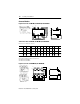
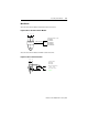
Control Circuits
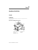
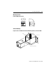
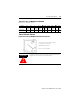
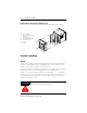
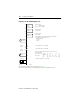
Figure 4.11 Smart Motor Manager Basic Unit
➊ Setting via communication is also disabled, as well as Test and Reset
➋ The remote reset is always active
13
14
97
98
95
96
95
96
97
98
13
14
Supply: A1 -
A1 +
Y11
Y12
Y13
Y21
Y22
Emerg.
Start
Disable
Settings
Remote
Reset
Supply AC or DC
No fuse needed
Emergency override of thermal trip
(Emergency start):
Push button, key-switch
Disable settings and keys: ➊
Wire jumper, switch, key-switch
Remote reset: ➋
Push button, key-switch
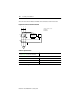
Alarm relay AL, non-fail-safe
connection (Factory setting)
IEC 400V AC/125V DC
UL/CSA 240V AC/125V DC
Alarm relay AL, electrically held
connection (from V2.18, selectable)
IEC 400 VA/125V DC
UL/CSA 240V AC/125V DC
Output relay MR in electrically held
connection (Factory setting)
IEC 400V AC/125V DC
UL/CSA 240V AC/125V DC
Output relay MR in non-fail-safe
connection
IEC 400V AC/125V DC
UL/CSA 240V AC/125V DC
External Internal