
User Manual Manual

4-5 Assembly and Installation
Publication 825-UM001B-EN-P January 2001
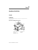
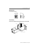
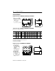
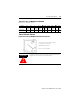
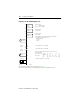
Figure 4.7 Basic Unit Housing with Option Cards
Normally the basic unit will be ordered and shipped with the required option cards.
Installation and Wiring
General
The Smart Motor Manager fulfills the stringent requirements imposed by global standards
requirements regarding electromagnetic compatibility (EMC). This means that there is no
need to observe any special stipulations when wiring the unit.
Nevertheless, control leads should be laid separately from power leads. In the circuit diagrams
throughout this section, any special wiring requirements are specifically noted.
The data of the output circuits and control inputs are dealt with in Chapter2, Specifications—
Basic Unit and Converter Module. Throughout this manual, the contacts of the output relays are
shown in their normal working position (i.e., the Smart Motor Manager control voltage is
switched on, no warning, no trip).
ATTENTION
!
All assembly and installation work must be performed by qualified
personnel, taking local codes into account.
CM
V4/CLV
4
Basic
CS
T4
C
P
B4
➊
➏
➋➌➍➎
➐
➊ Basic Unit housing
➋ Cat. No. 825-MMV or 825-MLV
option card
➌ Communication board
➍ Cat. No. 825-MST option card
➎ Board with basic unit
➏ Rear cover
➐ Screws