
User Manual Manual

Assembly and Installation 4-4
Publication 825-UM001B-EN-P January 2001
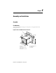
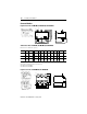
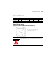
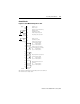
Table 4.B Cat. Nos. 825-MCM630, 825-MCM630N
Dimensions in millimeters (inches)
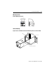
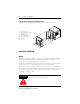
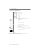
Thermal Utilization Indicator
Figure 4.6 Cat. No. 825-MTUM Thermal Utilization Indicator
Cat. No. a b c c1 ∅
∅∅
∅ dd1 d2 d3 ∅
∅ ∅
∅ e1 e2
825-MCM630
155
(6-7/64)
145
(5-11/16)
156
(6-1/8)
118
(4-5/8)
6.3
(1/4)
6.3
(1/4)
135
(5-5/16)
88
(3-7/16)
M10
48
(1-7/8)
825-MCM630N
155
(6-7/64)
145
(5-11/16)
177
(6-31/32)
118
(4-5/8)
6.3
(1/4)
6.3
(1/4)
135
(5-5/16)
88
(3-7/16)
M10
48
(1-7/8)
ATTENTION
!
To retrofit or replace options, the assembly and testing instructions
supplied with the option must be followed exactly.
Panel cutout: 91.5 x 91.5 mm (3-39/64" x 3-39/64")
(–1 mm [–1/16"] + 0.5 mm [+1/32"])
Mounting depth: 55 mm (2-3/16")
Wire size: 2 x 2.5 mm
2
(14 AWG)