
User Manual Manual

4-3 Assembly and Installation
Publication 825-UM001B-EN-P January 2001
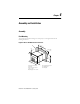
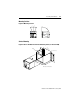
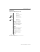
Converter Modules
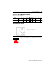
Figure 4.4 Cat. Nos. 825 MCM2, 825-MCM-20, 825-MCM180
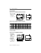
Table 4.A Cat. Nos. 825 MCM2, 825-MCM-20, 825-MCM180
Dimensions in millimeters (inches)
➊ Mounted on DIN Rail EN 50 022-35
➋ Bus bar or opening for conductor max. ∅ 19 mm
➌ With Cat. No. 825-MVM
➍ With Cat. No. 825-MVM2
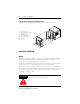
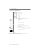
Figure 4.5 Cat. Nos. 825-MCM630, 825-MCM630N
Cat. No.
825-
abcc1∅
∅ ∅
∅ dd1 d2 d3 ∅
∅ ∅
∅ e ∅
∅ ∅
∅ e1 e2 b1 b2
MCM2
120
(4-45/64)
85
(3-23/64)
102
(4)
66
(2-39/64)
5.3
(3/16)
5.3
(3/16)
100
(3-7/8)
55
(2-3/16)
2 x
2.5 mm
2
—
38.5
(1-1/2)
——
MCM20
120
(4-45/64)
85
(3-23/64)
102
(4)
66
(2-39/64)
5.3
(3/16)
5.3
(3/16)
100
(3-7/8)
55
(2-3/16)
2 x
2.5 mm
2
—
38.5
(1-1/2)
——
MCM180
120
(4-45/64)
—
102
(4)
72
(2-13/16)
5.3
(3/16)
5.3
(3/16)
100
(3-7/8)
55
(2-3/16)
M8 M8
38.5
(1-1/2)
75
(2-61/64)
➌➍
100/117
d3
b
b
e2
e2
d2
a
c1
c
ø e
➊
➋
d1
ø d
➌
e2
e2
d2
a
d3
b
c1
c
d1
ø e
ø e1
ø d