
User Manual Manual

Publication 825-UM001B-EN-P January 2001
Chapter
4
Assembly and Installation
Assembly
Flush Mounting
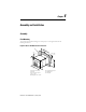
To mount the Smart Motor Manager in a front panel, cut a rectangular hole with the
following dimensions.
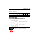
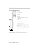
Figure 4.1 Basic Unit Mounted in an Enclosure
Alarm
Values
Select
Settings
Reset
Test
A
c
t
u
a
l
S
e
t
E
n
t
e
r
C
h
a
n
g
e
Tri p
R
e
c
o
r
d
e
t
138 mm
+ 1
- 0
1
4
4
m
m
(
5
-
1
1
/
1
6
"
)
144 mm
(5-11/16")
1
0
m
m
(
3
/8
"
)
max. 6 mm
(1/4")
1
3
8
m
m
+
1
-
0
(
5
-
7
/
1
6
"
)
+
1
/1
6
-
0
(5-7/16" )
+ 1/16
- 0
➊
➌
➋
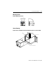
Dimensions in mm (inches) ➊ Front panel with cutout
Dimensions: ➋ Rubber gasket
Panel cutout: 138 x 138 mm ➌ Fixing nuts
(-0 mm, +1 mm)
Mounting depth: min. 140 mm