
User Manual Manual


Functions 3-52
Publication 825-UM001B-EN-P January 2001
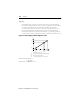
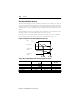
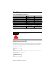
Figure 3.31 Operating Diagram for Timer Functions
Applications
• Time-graded switching on and off
• Delaying the transfer of alarm and trip messages
Lock-Out of Protection Functions
With control inputs #1 and #2, one or more protective functions can be locked out as
desired.
• Asymmetry (phase unbalance)
• High overload/jam
• Earth (ground) fault
• Short-circuit
• Underload
• Limiting the number of starts/hour
• PTC
• PT100
Applications
Lock-out of protection functions
During certain operational phases when the level differs from the normal values, such as:
• during starting: earth fault and short-circuit protection
• at no-load: protection against asymmetry and underload
• during brief overload phases: high overload/jam
• during commissioning and fault location (localizing the source of the trouble)
> 0.5 s
t
on
t
off
= 0
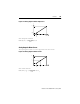
t
on
= 0
t
off
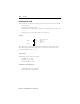
t
on
t
off
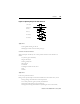
t
on
t
off
Control input
Output relay
On-delay
Off-delay
On-off-delay
On-off-delay