
User Manual Manual

Functions 3-26
Publication 825-UM001B-EN-P January 2001
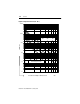
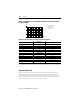
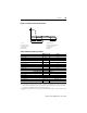
Figure 3.12 Function of Underload Protection
1 Start
r
Tripping threshold
2 Nominal operation t
s
Delayed activation (underload
3 Underload operation protection not active)
t
A
Starting time t
v
Tripping delay
e
Rated current t
p
Warning
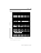
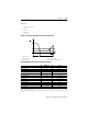
Table 3.N Underload Setting Parameters
➊ –5…60 °C (23…140 °F)
➋ For warning, the set Response Level is the same as the level set for tripping. If the starting current is below
1.2 FLC, then the “Monitoring the Start Time” function must be activated. After the set max. starting Time
has elapsed, the “High Overload/Stall” function will become active.
➌ If auxiliary relays #2 and #3 are assigned to the communication (refer to page 5-16) they cannot be selected
here.
Warning ➊ Tri p ➊
Function
Factory setting Off On
Response Level
Setting range ➋
25…100%
e
Factory setting ➋ 75%
Setting increments ➋ 5%
Tripping Delay
Setting range — 1…60 s -0.2 s/+0.4 s
Factory setting — 10 s
Setting increments — 1 s
Delayed Activation of Underload Protection
Setting range — 0…240 s +0.4 s/+0.8 s
Factory setting — 0 s
Setting increments — 1 s
Output Relay ➌
Selection (relays) AL, #1…#5 MR, AL, #1…#5
Factory setting AL MR
t
A
I
1
2
I
e
t
33
t
p
t
s
t
v
t
p
I
e
I
I
T