
User Manual Manual

Functions 3-22
Publication 825-UM001B-EN-P January 2001
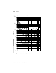
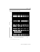
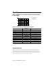
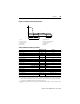
Table 3.K Protection Against Thermal Overload
➊ Thermal utilization %
➋ If auxiliary relays #2 and #3 are assigned to the communication (refer to page 5-16) they cannot be selected
here.
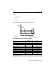
Asymmetry (Phase Unbalance) and Phase Failure
Asymmetrical phase voltages usually occur when the leads closest to the motor are too long.
The resulting current asymmetry in the motor windings may then be 6…10 times the voltage
asymmetry. The Smart Motor Manager takes into account the additional temperature rise and
thus prevents the life of the motor from being reduced. Higher asymmetry or the failure of a
phase can be caused by defective contacts in circuit breakers or contactors, loose terminals,
blown fuses, and faults in the motor itself. Rapid detection and interruption of these factors
help to prevent damage caused by overheating in such equipment. The stress on the
installation and the motor bearings is reduced. The Smart Motor Manager measures the phase
currents and calculates the total copper losses according to the definition of voltage
asymmetry per IEC and NEMA.
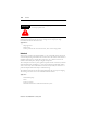
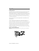
Definition of voltage asymmetry per IEC and NEMA:
Warning Trip
Function
Factory setting Off On
Response Level ➊
Setting range 55…99% —
Factory setting 75% 100%
Setting increments 1% —
Output Relay ➋
Selection AL, #1…#5 MR, No output relay
Factory setting AL MR
P
Cu
2
M
k
2
G
+()≈
∆U%()
Max. deviation from the average of the phase voltages 100×
Average of the phase voltages
-----------------------------------------------------------------------------------------------------------------------------
=