
User Manual Manual

3-21 Functions
Publication 825-UM001B-EN-P January 2001
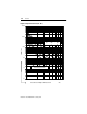
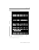
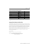
Table 3.J Thermal Overload Setting Parameters
➊ Up to 2 000 A, if primary current transformers are used.
➋ –5…60 °C (23…140 °F)
➌ UL/CSA 160…434 A
➍ The cooling factor can be modified to reflect different motor cooling with running motor and at standstill.
Detection Module ➋
825-MCM2 825-MCM20 825-MCM180 825-MCM630 825-MCM630N
Rated Current
Setting range 0.5…2.5 A ➊ 2.5…20 A ➊ 20…180 A 160…630 A ➌ 160…630 A
Factory setting 20 A 20 A 20 A 20 A 20 A
Setting increments 0.01…2 A 0.1…2 A 1 A 2 A 2 A
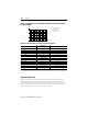
Locked-Rotor Current (Multiple of Rated Current)
Setting range
2.5…12
e
Factory setting
6
e
Setting increments
0.1
e
Locked-Rotor Time (Admissible Locked-Rotor Time of Cold Motor)
Setting range 1…600 s
Factory setting 10 s
Setting increments 1 s
Cooling Factor of Motor Off/On ➍
Setting range 1…10
Factory setting 2.5
Setting increments 0.5
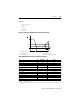
Resetting the Thermal Trip
Setting range 10…100% of thermal utilization
Factory setting 50%
Setting increments 1%
Ultimate Release Current
Incl. setting tolerance
1.05…1.15
e