
User Manual Manual
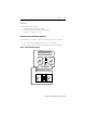

Functions 3-16
Publication 825-UM001B-EN-P January 2001
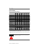
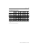
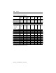
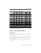
Table 3.I Control Functions Summary (Continued)
➊ For example, when used with two-speed motors
Functions of the Basic Unit (Cat. No. 825-M…)
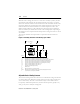
Thermal Overload
The Smart Motor Manager accurately simulates thermal conditions in the motor for all
operating modes. This permits maximum utilization of an installation and assures safe
protection of the motor.
The basic unit uses a two-body simulation to calculate a more precise representation of a
motor’s thermal condition during all modes of operation. A two-body simulation incorporates
the temperature rise characteristics of both the stator windings and the iron mass of the
motor into the thermal image.
The simulation of the Smart Motor Manager accurately represents the conditions in the
motor at all times.
Functions
Factory
Setting
Setting
Range
Factory
Setting
Tripping
Delay
Range
Factory
Setting
Relays
Selection
Factory
Setting
Bulletin 825-MST Option Card, Control Input #2: (24V AC/DC; 8 mA)
One of three functions can be selected:
1) Pickup delay, relay
#3
Off — — 0…240 s 1 s — #3
1) Dropout delay, relay
#3
—— —0…240 s2 s—#3
2) Set second rated
current ➊
Off
0.5…
2 000 A
20 A — — — —
3) Disable protective functions:
Asymmetry/phase
failure
Off — — — — — —
High overload/jam Off — — — — — —
Earth (ground) fault Off — — — — — —
Short-circuit Off — — — — — —
Underload Off — — — — — —
Limiting starts/hour Off — — — — — —
PTC Off — — — — — —
PT100 (RTD) Off — — — — — —
Bulletin 825-MLV Option Card
Star-delta starting Off —
Y-∆ at 1.1
e
Y-∆ at 1…240 s 10 s — Y: #4/∆:#5