
User Manual Manual

3-13 Functions
Publication 825-UM001B-EN-P January 2001
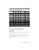
Function Summary
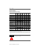
Table 3.G Protective Functions Summary
➊ Via external speedometer (control input #1), output and trip relays as for high overload.
➋ Allowing for the ambient temperature in the thermal image.
➌ Only one relay per function can be selected: MR = main relay, AL = alarm relay, auxiliary relay #1…#5 (if
auxiliary relays #2 and #3 are assigned to the communication [refer to page 5-16] they cannot be selected
here).
Functions
Factory
Setting
Setting
Range
Factory
Setting
Tripping
Delay
Range
Factory
Setting
Relays ➌
Selection
Factory
Setting
Bulletin 825-M… Basic Unit
Thermal overload On 100% — — MR, No MR
Asymmetry (phase failure) On 5…80% 35% 1…25 s 2.5 s All MR
High overloading/jam On
1…6
e
2.4
e
0.1…5 s 0.5 s All MR
Underload Off 25…100% 75% 1…60 s 10 s All MR
Underload delayed enable On — — 0…240 s 0 s — —
Earth (ground) fault (residual) On 10…100% 50% 0.1…5 s 0.5 s All MR
Starting time monitor Off — — 1…240 s 10 s All MR
Limited starts per hour Off 1…10 2 — — All MR
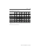
Bulletin 825-MST Option Card
Short-circuit Off
4…12
e
10
e
20…990 ms 50 ms #1, No #1
Earth (ground) fault
(core balance c.t.)
Off 5 mA…50 A 1 A 0.1…5 s 0.5 s All MR
Stalling during start Off — ➊➊—All ➊ MR ➊
Thermistor input (PTC) Off — — — 800 ms All MR
Bulletin 825-MLV Option Card
Phase sequence (motor supply) Off — — — 1 s All MR
Phase failure (motor supply) Off — — — 2 s All MR
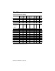
Bulletin 825-MMV Option Card
PT100 input #1…#6 (RTD)
(stator, bearings)
Off 50…200 °C 50 °C— <8 s
MR, AL
#1…#3
MR
PT100 input #7 (RTD) ➋ Off——————
ATTENTION
!
Warning function settings must be such that associated alarms are
actuated before a trip occurs.