
User Manual Manual

Equipment Description 2-13
Publication 825-UM001B-EN-P January 2001
Automatic Recognition of Converter Module
The Bulletin 825 regularly checks:
• The link between the basic unit and the converter module
• Verifies that the full load current set on the basic unit is within the range of the
converter module
• The supervisory circuits
In the event of a fault, the output relay MR trips and the type of fault is displayed on the LCD.
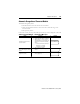
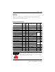
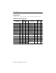
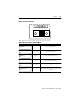
Table 2.I Converter Module — Related Error Messages
Verify Sequence Display
Link between basic unit and
converter module
• After switching on supply
• Supervision while motor is stationary
• When running, as soon as the link is
interrupted the basic unit will trip and
display one or more of the following
causes:
• short circuit, thermal, earth fault
(Holmgreen = residual),
asymmetry, overcurrent
Verification that FLC on basic
unit is within range of converter
module
• After switching on supply
• After each change in setting of rated
current
Supervisory circuits
• Continuous monitoring (hardware
errors, supply, etc.)
825-MCM NOT CON
Ie OUT OF RANGE
ERROR 825-MCM