
User Manual Manual

2-6 Equipment Description
Publication 825-UM001B-EN-P January 2001
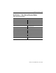
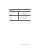
Table 2.B Nominal Rated Voltages U
e
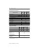
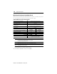
Table 2.C Electrical Ratings
➊ The measuring inputs for PT100 and PTC, the 4…20 mA output, and the communication interface are not
isolated from one another.
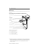
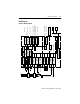
Primary Detection Circuit
825-
MCM2
825-
MCM20
825-
MCM180
MCM630
MCM630N
Motor Circuit
as per IEC, SEV, VDE 0660 400V AC 660V AC 1 000V AC
as per CSA, UL 240V AC 600V AC 600V AC
Control Circuit
Main relay (MR) 95…98, supply A1, A2
Phase sequence protection L1, L2, L3
as per IEC 947 400V AC
as per SEV 380V AC
as per UL, CSA 240V AC
Alarm relay (AL) 13/14
Auxiliary relay #1, #4, #5
as per IEC 947 400V AC
as per SEV 250V AC
as per UL, CSA 240V AC
Auxiliary relays #2, #3 50V AC/30V AC
Control inputs #1, #2 24V AC/DC
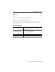
Test Voltage
825-
MCM2
825-
MCM20
825-
MCM180
MCM630
825-MCM630N
Motor Circuit
as per IEC 947-1
U
imp
2.5 kV
U
imp
6 kV
U
imp
8 kV
U
imp
12 kV
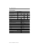
Control Circuit
Between control circuits and to all other circuits ➊
Main relay (MR) 95…98,
supply A1, A2
Phase sequence protection
L1, L2, L3
Alarm relay (AL), auxiliary relay
#1, #4, #5 as per IEC 947-4
U
imp
4 kV
Core balance current transformer k, I
Control inputs #1, #2
Auxiliary relays #2, #3
as per IEC 947-4
U
imp
2.5 kV