
User Manual Manual
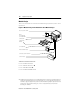
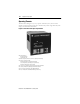

Equipment Description 2-3
Publication 825-UM001B-EN-P January 2001
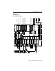
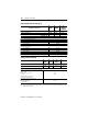
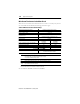
Block Diagram
Figure 2.2 Block Diagram
Controller
Basic unit
825-M
Operation
Remote reset
Thermistor
overload
T1, T2
Phase
sequence
L1
Phase failure
L3
L2
PT100 #1…#6
(RTD)
1T1/1T2/1T3
…6T1/6T2/6T3
PT100 #7
(RTD)
7T1/7T2/7T3
Earth fault
k, l
Y11
Y13
Emergency start
Disable settings
Y12
LCD
Supply
Main relay MR
95/96
97/98
Alarm relay AL
13/14
Auxiliary relay #1
23/24
Auxiliary relay #2
33/34
Auxiliary relay #3
43/44
Analog output
I+ / I-
Auxiliary relay #4
53/54
Auxiliary relay #5
63/64
Communication Interface
Stator /
bearing temperature
Ambient temperature
4…20 mA
Warning/Trip
825-
MCM
∑
M
3 ~
amb
ϑ
L1
L3
L2
F
825-M
825-MST
825-MLV
825-MMV
L1 L 2 L 3
Y22
Y21
Choice
825-MLV or 825-MMV
PC
PLC
Network
A2 (+)
-
+
A1 (-)
Control
inputs
Y31
#1
#2
Y32
24 V AC/DC
Y41
Y42
24 V AC/DC
825-MDN
3600-RIO
3600-MBS
825-MPB