
User Manual Manual

9-3 Applications/Wiring
Publication 825-UM001B-EN-P January 2001
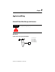
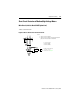
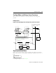
Star-Delta Starter with Bulletin 825 Smart Motor Manager
Main Circuit
Figure 9.3 Basic Unit and Converter Module
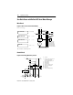
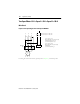
Control Circuit
Figure 9.4 Control by Momentary Contact
825-MCM
825-M
L1 L2 L3
M
3~
1
35
246
1
3
5
2
4
6
1
3
5
2
4
6
A1
A2
K1H
A1
A2
K2D
A1
A2
K3Y
U1
F1
L
s
1)
U1 V1
W1
U2
V2 W2
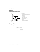
Basic Unit settings:
FULL LOAD CURR
LOCKED ROT CURR
LOCKED ROT TIME
START TIME
FLC x 0.5774 [A]
BL∆
(…x
e
)
BL∆
(…sec.)
> t
startY
(…sec.)
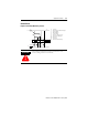
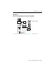
U1 Converter module
Cat. No. 825-MCM2
Cat. No. 825-MCM20
Cat. No. 825-MCM180
Cat. No. 825-MCM630
Cat. No. 825-MCM630N
➊
➊ Core balance installation position
AL
A195 97
96
98 A2
A1
A2
(L2/F8)
N
H1
K1
H3
825-M
13
14
F7
L1
S0
S1
MR
F1
U
s
A1
A2
53 63
54
64
825-MLV
F1
A1
A2
K3 K2
D
K1
H
H2
K1 Contactor
F1 Electronic control and protection
system Bulletin 825 with
Cat. No. 825-MLV option card
S1 On push button
S0 Off push button
U
s
Control voltage
H1 Indicator “Contactor closed“
H2 Indicator “825-M tripped“
MR Main relay
AL Alarm relay
H3 Indicator “Alarm/Warning“